Addition of Antisidetone Circuit to Vintage Telephones
General
On his
website, Colin Chambers describes an anti-sidetone network circuit to put in the base of a vintage phone that uses an external ringer box. Having five such phones, I decided to build the circuit and update my old phones. The 600-ohm-center-tapped to 600-ohm-center-tapped transformers were only $2.00 each, or $2.50 each with shipping, for five transformers. But no surprise, each phone was different, so I had to come up with a different wiring diagram for each phone.
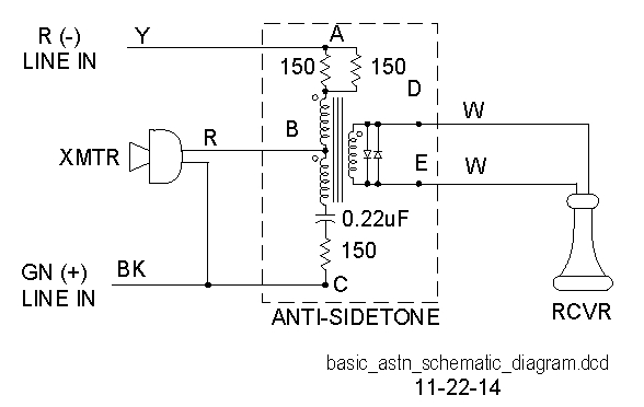
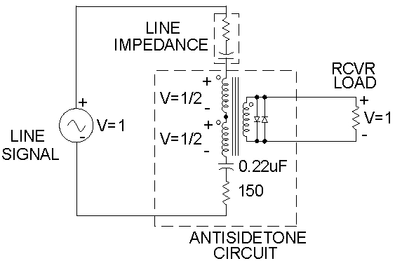
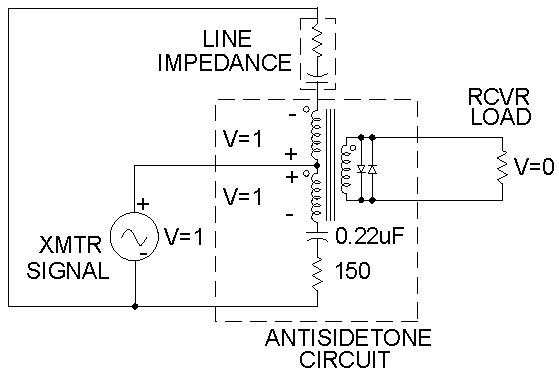
Basic Circuit
Layout Requirements:
Small, low profile
Easy to build
Cut spaces between tracks instead of etching
Straight cuts to make cuts easier
Cheap transformer, Mouser 42TL016-RC, specified to take only 100 volts for 1 minute, but it is okay as it only sees line voltage of 48 volts and not ringing voltage
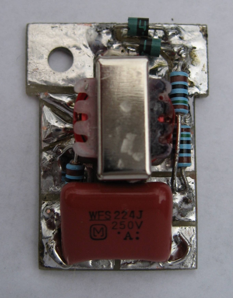
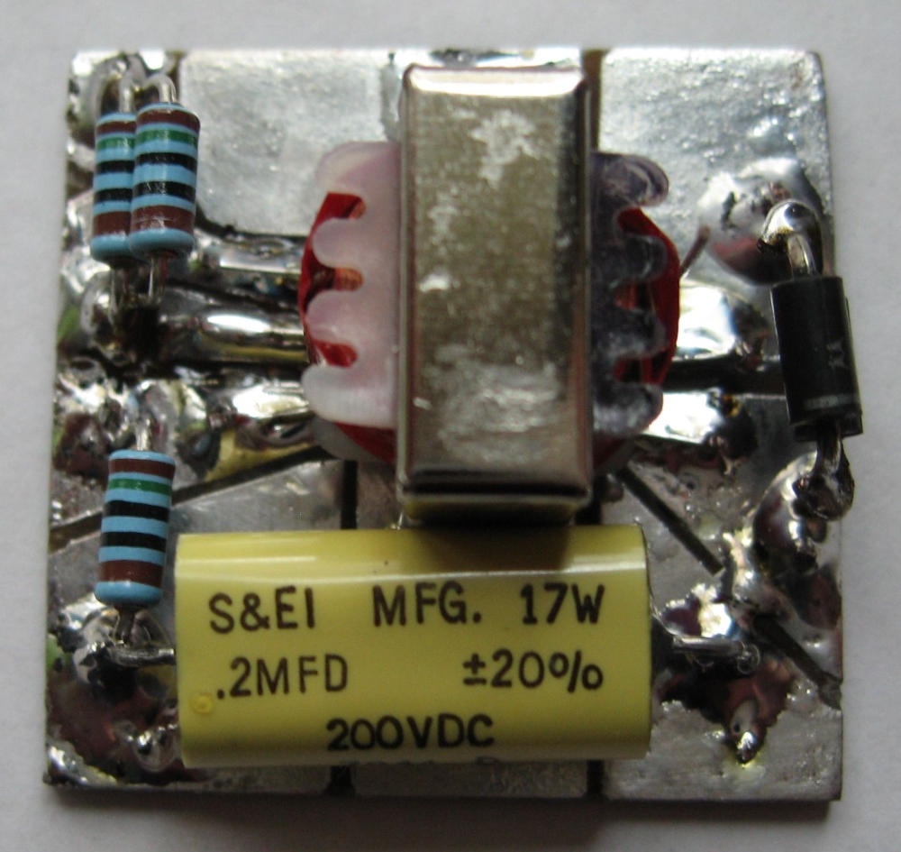
Circuit
Tested boards
Phones:
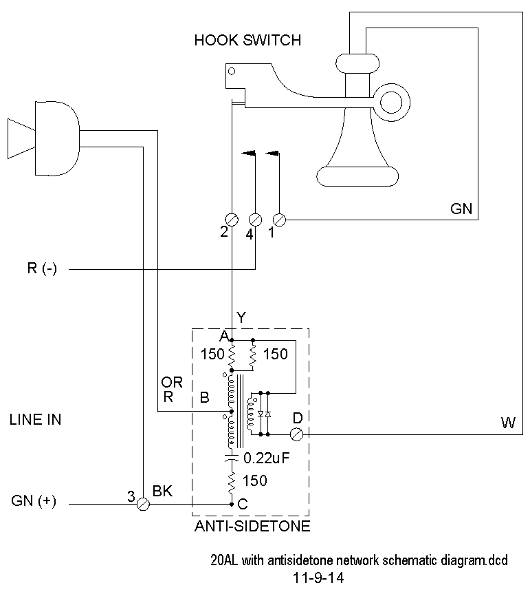
1910 Western Electric 20AL with no dial
1910
Western Electric 20AL
3PPC hook switch
(3-pole Progressive Contact)
|
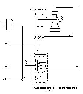
1910 Phone With
Anti-Sidetone Circuit
Schematic diagram
|
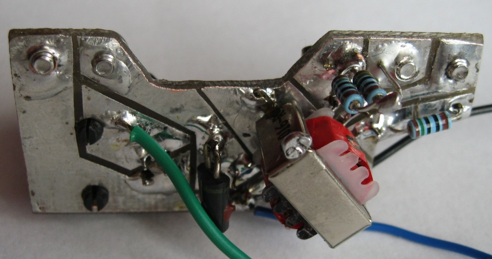
Stem Board
mounted in 1910 phone
|
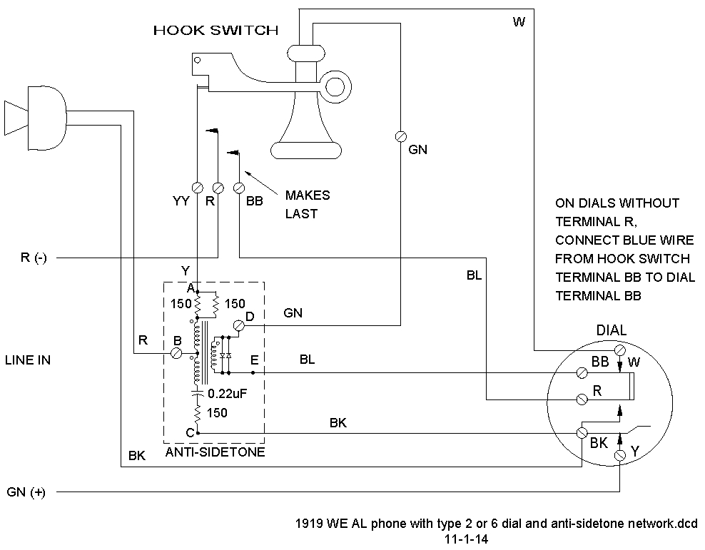
1919 50AL with Western Electric type five dial.
1919
Western Electric 50AL
Western Electric type 5H dial
3PPC hook switch
Two 1P1T dial off-normal switches
Normally-closed leaf connects
receiver until dialing,
at which time the receiver
connection is opened.
Normally-open leaf
shorts the line during dialing.
|
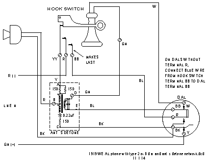
1919 Phone With
Anti-Sidetone Circuit
Schematic diagram
|
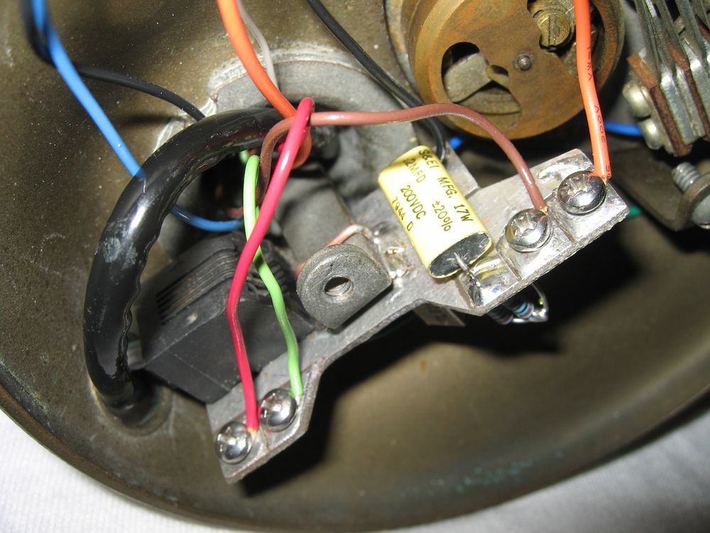
Board with Connector
mounted in 1919 phone
|
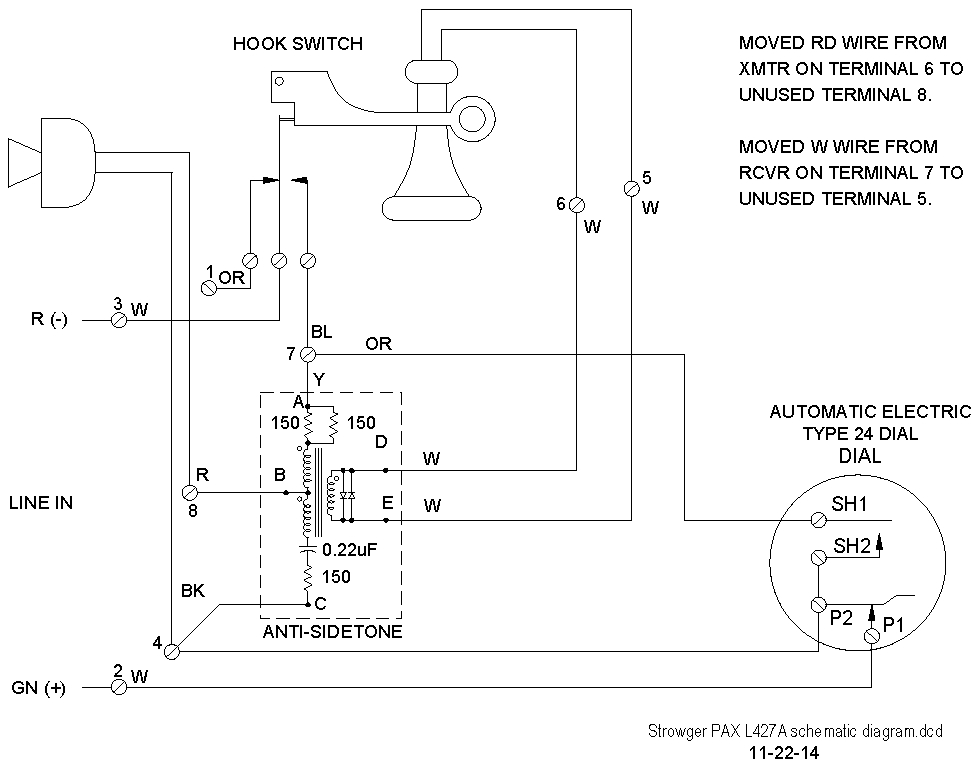
1922 Automatic Electric Type 21 Strowger PAX L427A with Automatic Electric type 24 dial
1922
Strowger PAX L427A
Automatic Electric type 24 dial
1P2T hook switch
1P1T dial off-normal switch
Dial 1P1T off-normal switch
leaves are open until dialing.
|
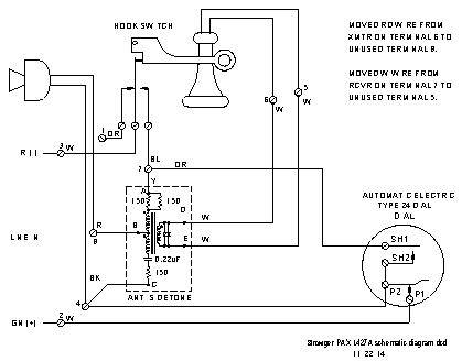
1922 Strowger PAX L427A Phone With
AE Type 24 Dial
Anti-Sidetone Circuit
Schematic diagram
|
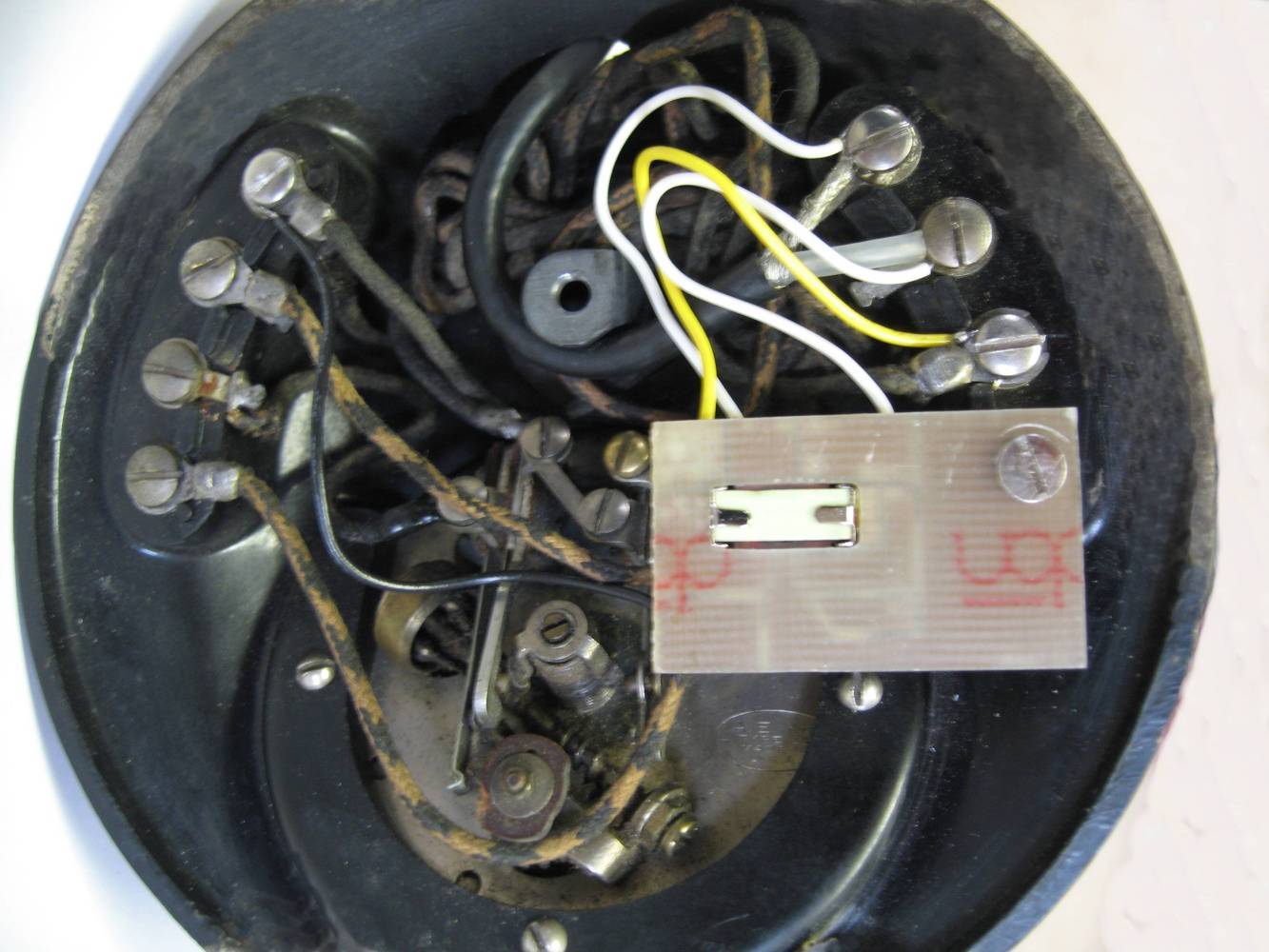
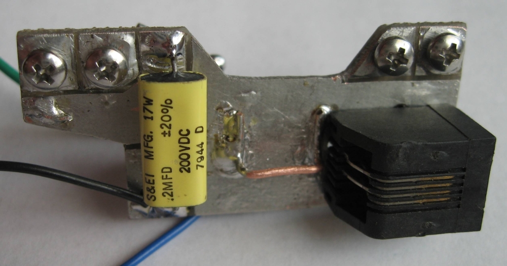
Strowger Board
mounted in 1922 phone
|
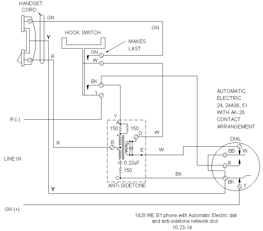
1928 B1 base mount with Automatic Electric type 51A dial that has an AK-26 Western Electric switch stack (will work with Western Electric type 2 dial)
1928
Western Electric B1 base mount
Automatic Electric type 51A dial
with AK-26 AE switch
stack or
Western Electric type 2 dial
2P2T hook switch
1P2T dial off-normal switch
Dial 1P2T off-normal switch
center leaf connects
receiver until dial center leaf
switches during dialing to
short the line, at which time
the receiver connection is
opened.
|
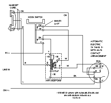
1928 B1 Phone
With WE Type 2 Dial
Anti-Sidetone Circuit
Schematic diagram
|
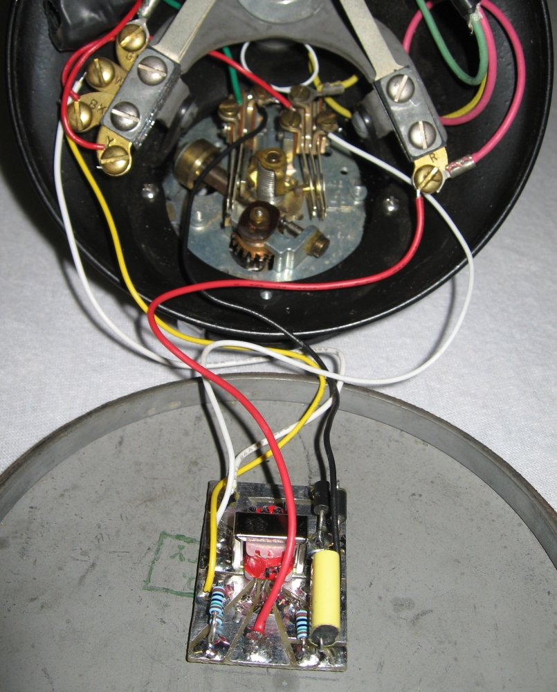
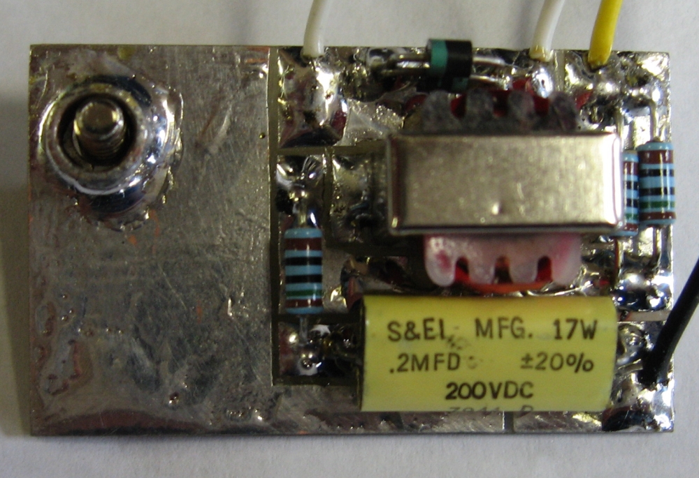
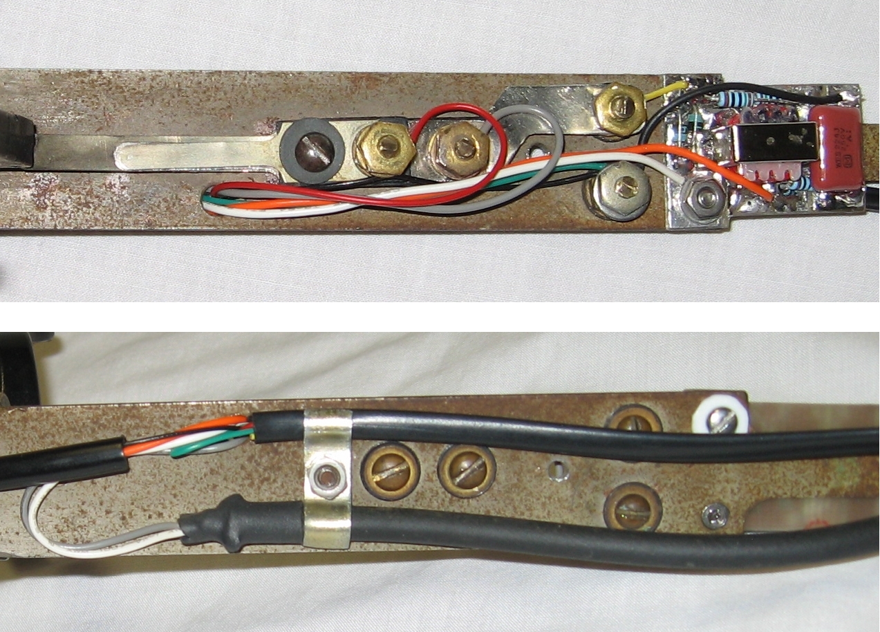
Large Board
mounted in 1928 phone
|
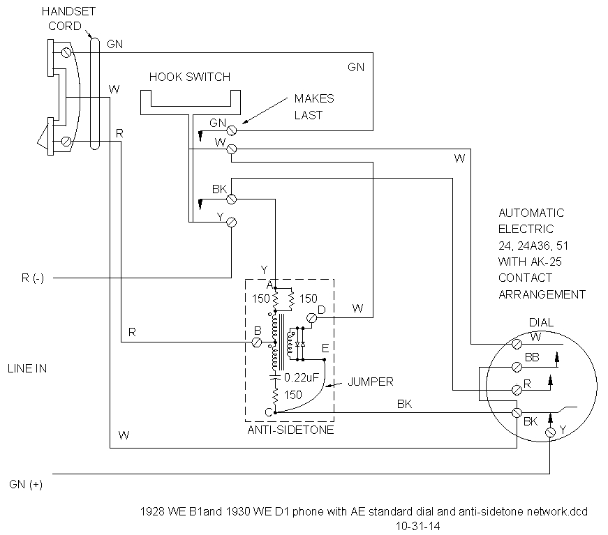
1928 B1 base mount with Automatic Electric type 51A dial that has an AK-25 AE standard switch stack
1930 D1 base mount with Automatic Electric type 51A dial that has an AK-25 AE standard switch stack
1928
Western Electric B1 base mount
1930
Western Electric D1 base mount
Automatic Electric type 51A dial
with AK-25 AE standard switch
stack
2P2T hook switch
3PPC dial off-normal switch
Dial 3PPC off-normal switch
leaves are open until dialing.
The first two leaves short
the receiver before the third
leaf connects to short line.
|
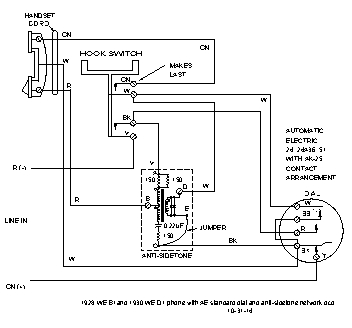
1928 B1 or 1930 D1 Phone With
AE Type 51A Dial
Anti-Sidetone Circuit
Schematic diagram
|
Large Board
mounted in 1928 phone
|
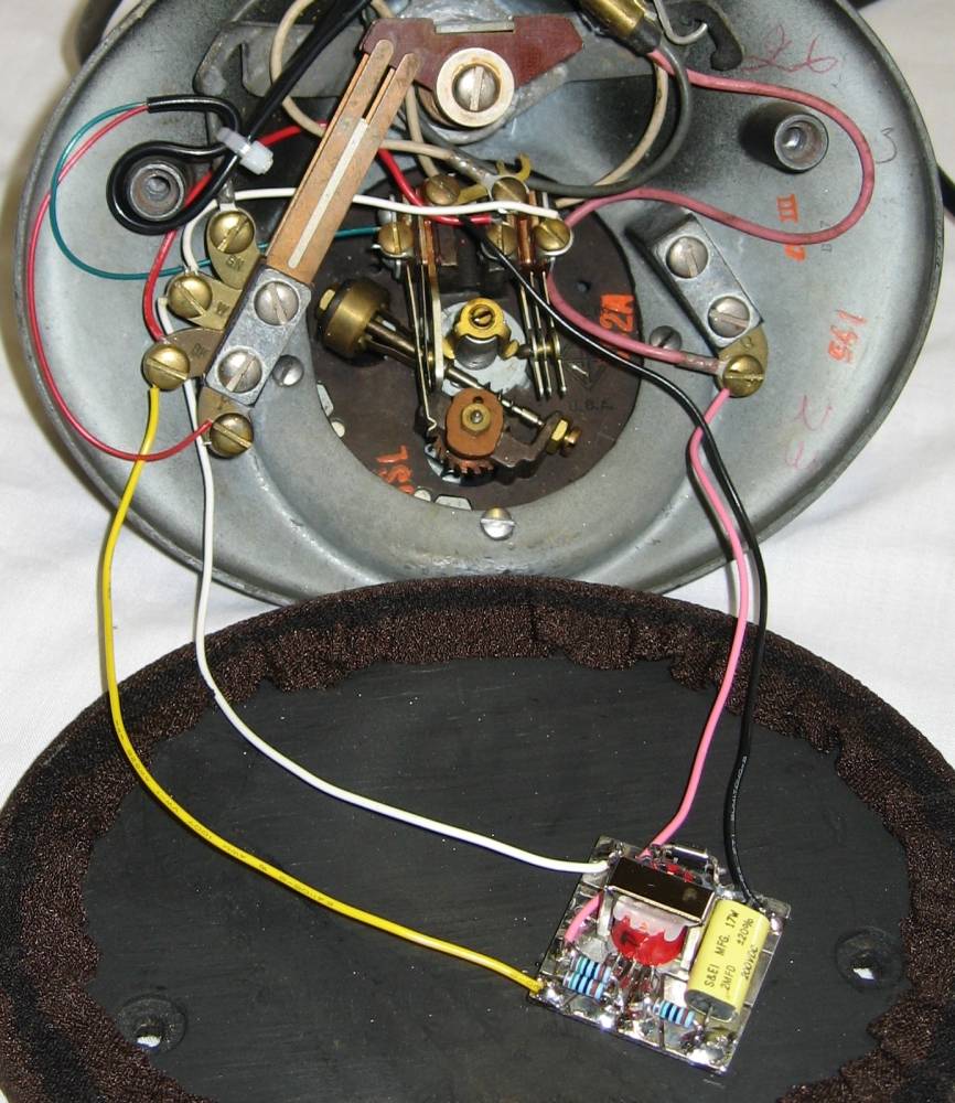
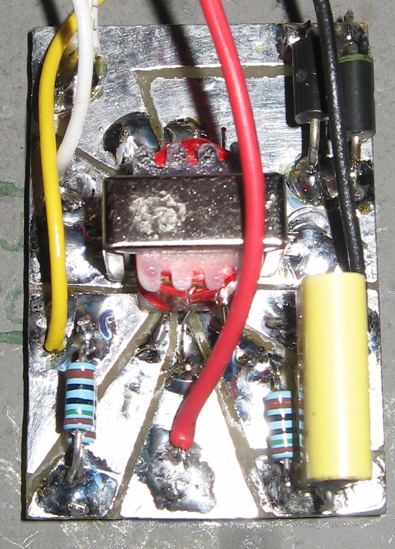
Small Board
mounted in 1930 phone
|
Performance
Mixed. All phones sounded better than the 600-ohm-to-900-ohm autotransformer I was using before. The 1910 had the least sidetone reduction, the 1930 the best. The 1919 was hardest for the called person to hear, the 1910 was easiest. There is a lot of variance in the transmitters and receivers used in these phones, so I an not surprised by the variance in sidetone reduction.
All of the phones worked well with modern phones also on the line, so it seems the addition of this circuit keeps the old phones from loading down the line.
Copyright Dale Thompson,
November 10, 2014 through
last revision on November 26, 2014