There is not much room in the base of this phone, and there is a wiring diagram glued to the bottom plate of the base. Preservation of the wiring diagram meant that the antisidetone board could not be adhered to the bottom plate with tape, so a small low-profile board had to be built that could be held in place by a counter sunk screw in an unused terminal. The transformer is recessed into the board to keep the profile as low as possible. Other than that, the board is similar to the other boards and was made by scoring two parallel lines on the the copper with an Xacto knife for each needed separation, then peeling the copper between the lines off of the circuit board. After the separations were made, the board was sanded, and then, tinned using a water-soluable solder paste. Components were surface mounted. A pigtail modular plug was used with a 20-inch cord, short enough so I would not have an unsightly wire lying around where the phone is displayed, but long enough to plug in to a counter-level socket for testing and demonstrating. Young people just don't believe these old phones still work.
Click on the photos below for construction details and photos.
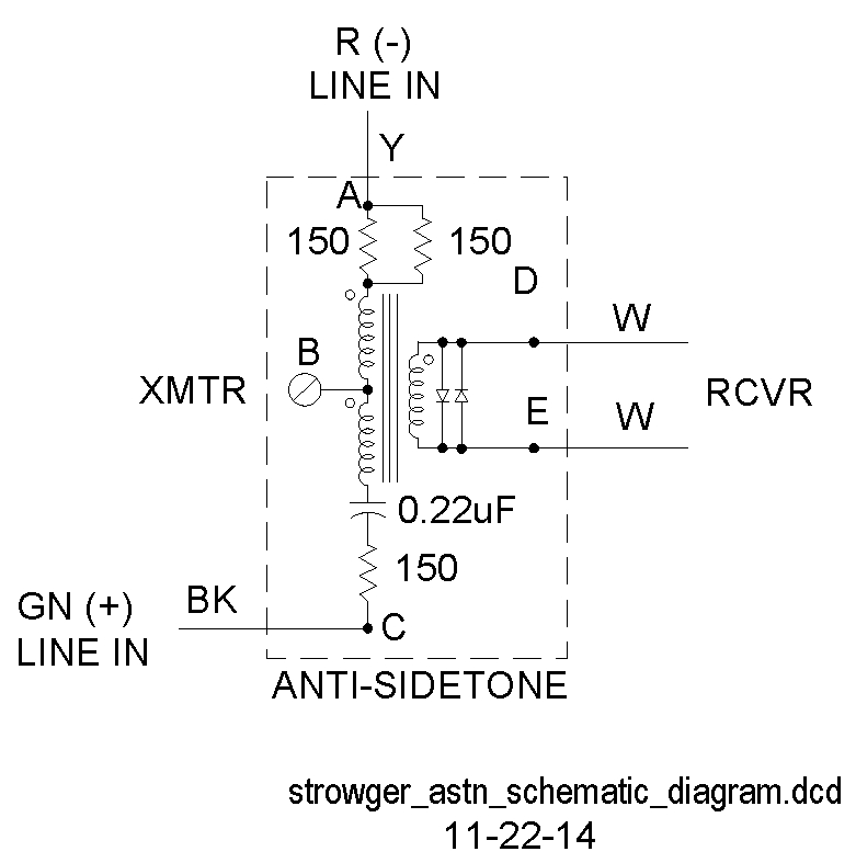 Antisidetone Circuit |
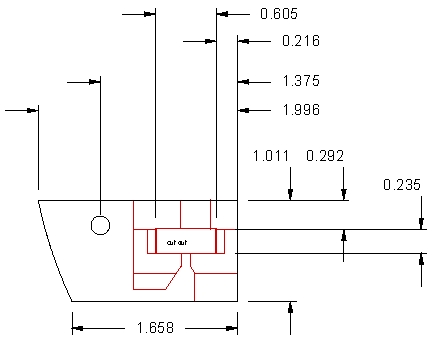 Board Artwork |
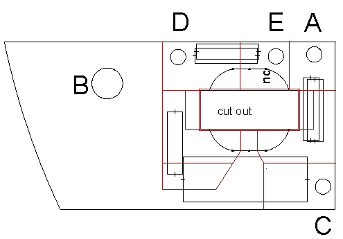 Component Placement |