Klipsch Promedia V5.1 Amplifier
Block and Interconnect Diagrams
A Promedia 4.1 on steroids.
Take a V2-400 and use the sub-woofer amplifier for the center channel. Then add a separate Digital Converter just for the added sub-woofer amplifier and you have the starting of a V5.1. Next, put all the preamplifiers in the sub-woofer box and make a digital control box to remotely set the preamplifier gain controls.
You have a V5.1.

Block diagram of Indigo BASH amplifier in Klipsch Promedia V5.1
|
Below are the interconnections for the system. The control pod and the satellite speakers shown are separate units; all other connections are internal to the subwoofer box.
Interconnect diagram of Klipsch Promedia V5.1
|
Control Pod
There is not much you can do about repairing the V5.1 control pod. Klipsch moved all the pre-amplifier circuitry into the sub-woofer box. The control pod is just a remote control head now. A serial data stream from the control pod relays commands to adjust the volume level of the various channels. All the manual inputs are rotary encoders that are monitored by a microcontroller. With the exception of the encoders and a few transistors everything is done by the microcontroller program, which you can't buy from Klipsch and for which we don't have any data. Maybe someone can come up with an analog replacement circuit.
The following block diagram of the control pods is marked to show basic operation of the pods and the differences between them. Click on the block diagram, or
here to get schematic diagrams of the two control pods.
Block diagram of Control Pod Boards
|
Unlike previous versions, the DIN cable for version 5.1 has two pod connectors on one end and the DIN connector on the other end.
The diagram for the V5.1 DIN plug comes from tracing of the wires by Evan Shultz on his plug. Pins are identified by using the pin numbers on the control pod circuit board connector, J2 ,then continuing the sequence with the signals from J6 on the standard pod or J1 on the Ultra pod.
The diagram is shown looking at the mating side of the plug pins and not the soldered side.
V5.1 Mini-DIN Connector Wiring Diagram
|
I/O Board
The V5.1 I/O board is very busy. The control pod is just that on the V5.1, a control pod, so all the audio preamplifiers and headphone amplifiers had to be moved into the subwoofer box. Breaking the I/O board down, we have seven sub-sections: the front-channel preamplifiers, the rear-channel preamplifiers, the center-channel preamplifier, the subwoofer filter, the headphone amplifiers, the headphone/control-pod power supply, and the control-pod, serial-data circuits.
All the preamplifiers are similar. A 2X gain stage, like center-channel U4:3, supplies a signal to the subwoofer filter and to the serial-data-controlled level adjuster U5. The level-adjusted signal is fed to the headphone amplifier summing circuit and to a high-pass filter that in turn drives the channel's power amplifier. The front-channel preamplifier adds summing amplifiers U3:1 and U3:2 to inject the subwoofer input and the auxililiary input from the control pod into the front-channel signal.
Subwoofer filter (U6:3, U5:6, U1:3, U1:2 and U1:1) is level controlled by U5:6. The filter is a a second-order, high-pass, Sallen-Key filter followed by a a second-order, low-pass, Sallen-Key filter resulting in a very narrow low frequency bandpass filter. U6:3 is a summing amplifier to combine the signals from the individual channel preamplifiers.
The headphone amplifiers are low-powered, push-pull, AB circuits with summed inputs from all the various preamplifiers. Relay K1 controls the function of the auxiliary-input/headphone-output jack on the control pod. In the un-activated state, K1 passes audio signals from the dual-purpose jack to the front-channel summing amplifiers U3:1 and U3:2. When headphones are selected on the control pod, the pod sends a HP-MODE, high-level logic signal to Q1. This activates K1 and the auxilary-input/headphone-output jack on the control pod is connected to the headphone amplifier outputs.
The headphone amplifiers and the I/0 board preamplifiers get their +/- 15V power from a power supply separate from the AC-DC converter. This low-power regulator is constantly active, and sourced by the transformer on the line-filter board. In this manner temperature inside the subwoofer box is reduced during the non-use periods when there is no air movement provided by the subwoofer speaker cone.
The +/- 15V supply also sources the main-power relay on the line filter board. A PWR-MODE high-level logic signal from the control pod activates the Q6/Q7 relay driver.
Finally, +5Vdc and the serial-data receiver for the control pod are on the I/O board. The reciever is U5:7, and decodes the serial data to adjust the level of all the preamplifiers.
Of course the I/O board has to provide passive input and output connections. The power amplifiers and the line filter plug directly into the I/O boad, and the spring clips for the satellite speaker connections are also directly mounted to the board. Likewise, the DIN cable connector is a direct mount. In fact, only the AC-DC Converter and the Digital Converter have separate pendant cables that plug into the I/O board.
Schematic diagram of I/O Board
Sheet 1 of 3
|
Schematic diagram of I/O Board
Sheet 2 of 3
|

Schematic diagram of I/O Board
Sheet 3 of 3
|
Line Filter
There is not much to say about the line filter. It is a common-mode, input, line-noise filter; a low-
voltage transformer; and a power relay. But don't ignore it. The relay is a known weak spot in the
system. When the relay fails, the low-voltage transformer still supplies power to the rectifiers and
regulators on the I/O board. The control pod is powered up and works okay, but there is no power to
the amplifier circuits.
Schematic diagram of Line Filter
|
Since the power relay has a high failure rate, I get asked about replacement parts. Th information below is from second-hand sources, that is sometimes called hearsay, and it is not admissible in court because it may be inaccurate. I have tried to verify the accuracy by examining the specification sheets of each relay and noting differences I have spotted.
The Rev. C board used a Goodsky EMI-SS-224DM. the table below list some possible replacements.
The Rev. E board used a Panasonic LK1AF-24V. the table below list some possible replacements.
AC to DC Converter
Unlike the V2-400 and the V4.1, the V5.1 can be turned on and off at the control pod. This was done by putting the input line filter and a relay on a separate board, and moving the input rectifier bridge to the DC-DC Converter, which became an AC-DC Converter. To get the extra components in the same or smaller space, Klipsch used a daughter board for the soft-start components, creating yet another high-failure point. Previously metioned was the unreliability of the relay. The second area, the daughter board, was a failure mode in both units Evan traced. He is working on a replacement board for the daughter board.
Line voltage from the Line-Filter Board is rectifier and applied to a self-oscillating push-pull converter used as an ideal transformer. The rectified line voltage is transformed and galvanically isolated to create a unipolar main rail for the buck converter; roughly 56 Vdc for the satellite converter and 85 Vdc for the sub-woofer converter. TH501 is an NTC thermistor that presents a low resistance to limit in-rush upon startup, but the resistance drops as it heats up. So the NTC has little effect once the supply is running. MR8 and MR9 divide the rectified DC input voltage so that MQ3 turns on at about 100VAC and MD2 avalanches. This turns on Q1 and the supply begins oscillating. Turning on one switch turns on the other switch the next cycle, and thus the supply is self-oscillating. Because of the operation of a push-pull supply, the voltage stress is high on the switches which is a hindrance because high-voltage switches must be used. However, at this relatively low power level it's not a big issue. The operation of this converter is covered in US patent US6108219.
The auxiliary voltages (+/-15) are created using a single winding that is full-wave rectified to create bipolar rails referenced to ground. The transformer windings used provide about +/-33V. While the auxiliary voltage is referenced to circuit ground, the buck converter's specific implementation means the main output is not ground referenced until the output of the buck converter. In addition to the +/-15V supplied, separate windings produce a +22V output referenced to the negative terminal of the floating 56Voutput and a +32V output referenced to the negative terminal of the floating 85Voutput.
Schematic diagram of AC to DC Converter
|
Layout of trouble-prone daughter board
|
Digital Converter
With another channel added, and increased output power desired, the Digital Converter used on previous models reached its limit. Klipsch solved this problem by duplicating the buck converter, putting two independent buck converters on on one Digital Converter board. Each buck converter operates in the same manner, so only one is described here.
The Promedia V5.1 uses a Class G "tracking" output stage (Class H outside of the US), which means that the rail voltage of the amplifier is held slightly higher than the level required to reproduce the audio signal. This reduces dissipation in the amplifier output stage greatly because the amplifier is only required to reproduce high output power for small amounts of time - most of the time the power required by the speakers to reproduce audio is very small. The rail-voltage-tracking power supply is simply a cleverly re-arranged buck converter with the inductor and switches in the return leg instead of the supply leg. This has the benefit of allowing ground-referenced, N-channel FETs to be used with simple, resistive current sensing. The disadvantage is that the feedback signal must be re-referenced from the output ground (which is circuit ground) to the input ground (floating with respect to circuit ground). The operation of a buck converter is covered extensively from many online sources and is not repeated here.
It is worth noting that current is sensed in only one of the FETs, meaning the converter relies on good matching of the FETs both electrically and thermally for protection from current hogging. Since FETs have a negative temperature coefficient , this is a reasonable tradeoff for a consumer product since it eliminates having to measure and combine the current from two parallel switches and provide protection for each switch separately.
Klipsch continues the use of 55V BVDSS IRFZ44N FETs in the 56V supply circuit, and relies on loading of the unregulated DC-DC converter and system voltage losses such as the current sense resistors to keep the devices from failing. For the 85V supply circuit, they used 100V BVDSS IRF530 FETs, a little better engineering. Output capacitors C2 and C9, are large film caps instead of the traditional electrolytics. They provide a low output impedance supply for the amplifier.
Schematic diagram of Digital Converter
|
Indigo BASH HC1012 Module
There is no HC1012 Module. The Digital Converter board has HC1012 silkscreened on it, but the board is stuffed with two HC1011 modules.
The HC1011 Module uses a UC3842A controller IC to drive the FETs in the Digital Converter in response to the demands fed to it by the Amplifier Board's AMP-LEVEL signal. A current threshold is established in the UC3842A by the AMP-LEVEL signal. Feedback of the rail voltage to the Amplifier Board at FB-IN reduces the threshold when the rail votage approaches the established point. In the UC3842A, the threshold sets the point where the I-SENSE voltage from the Digital Converter FET source resistor will cause the UC3842A to cut off the DRIVE output to the FET gates. Switching off the FET gate drive determines the pulse width of the buck converter in the Digital Converter, and in turn establishes the Amplifier Board rail voltage.
An AMP-OC circuit is incorporated in the Module that reduces the rail voltage if excessive current is being drawn by any of the Amplifier Boards.
For a more detailed description of the Module operation click here.

Schematic diagram of Indigo BASH HC1010 / HC1011 Module
|
Amplifier Board
There are six identical amplifiers on six separate boards plugged into the I/O board. The amplifier topology is a linear balanced full bridge. Audio is received, filtered, and buffered by U1:1. The audio signal from U1:1 is then inverted by U1:2.
The non-inverted and inverted audio signals from U1:1 and U1:2 are rectified by D1 and D2 to form a AMP-LEVEL signal. In turn, the AMP-LEVEL signals from the satellite-channel amplifiers are supplied to the I/O board where they are connected with all the other satellite-channel amplifier AMP-LEVEL signals. A combined AMP-LEVEL voltage tells the satellite-channel buck converter how high the amplifier rail voltage needs to be to allow the amplifier with the greatest audio signal to reproduce that audio signal.
The AMP-LEVEL signal from the sub-woofer-channel amplifier is passed directly through the I/O board to the sub-woofer-channel buck converter to keep that amplifier's rail voltage at the level needed.
Phase-opposed audio signals from U1:1 and U1:2 are filtered and mixed with feedback by both U1:3 and U1:4. Amplifiers U1:3 and U1:4 drive the class AB amplifiers forming the two opposite sides of the speaker driving bridge.
Resistor R45 measures the current flowing to the output stage. When output current reaches a threshold of about 9A, Q45 is turned on and supplies a AMP-OC signal to the I/O board. The AMP-OC signal continues to the Digital Converter where the buck converter is shut down in response to the overcurrent condition. Any of the five satellite amplifiers experiencing an overcurrent will trigger shutdown of the entire satellite-channel supply. The sub-woofer supply is independent of the satellite-channel supply, and is only shut down if an overcurrent is detected in the sub-woofer amplifier.
Schematic diagram of Amplifier Board
|
Photo Gallery
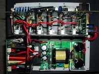
CW from top: I/O board, 6 Amplifier boards, line filter, AC-DC, dual Converter.
|
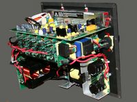
Oblique view of unit.
|
Copyright Dale Thompson.
January 13, 2009 through
last revision on September 12, 2012