Klipsch Promedia V5.1 Control Pods


The Standard and Ultra Control Pods


I refer to the two control pods used with the V5.1 system as the standard pod and the Ultra pod. By standard I mean the contol pod supplied withthe original V5.1 system. It didn't really have a name; it was just the control pod. The Ultra control pod came out with the V5.1 system, and is referred to by Klipsch as the Ultra control pod.

There is not a lot of difference between the standard and the Ultra pods. Differences are mainly cosmetic.


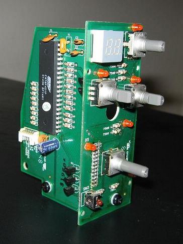
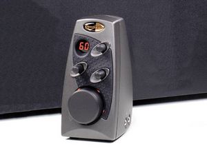
V5.1 Standard Control Pod


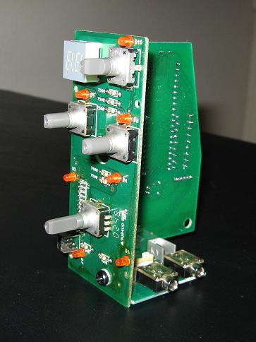
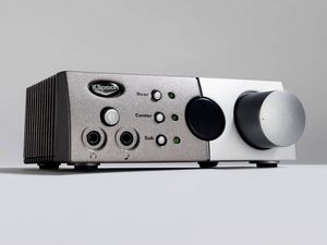
V5.1 Ultra Control Pod


When you plug an AC cord into the V5.1 system, nothing happens. Internally, the auxilliary transformer starts working and the +5V rail is created for the microprocessor, but nothing externally happens. When the power button on the control pod is pressed, the BASH sections come alive and the amplifirs awaken. The main volume level is displayed and defaults to '40'. When the power button is pressed again, the main, rear, sub, and center levels are saved, the amplifiers turn off, and the microprocessor switches the relays to make the headphone output active. During this power-off time, the dual-digit LED displays 'HP'. After that, the dual-digit LED display changes to the headphone level. When you hit the power button again, the relay switches back to an input, the amplifiers wake up, and the main, rear, sub, and center levels are restored.

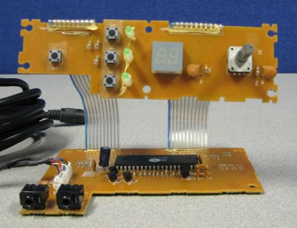
The control pod is an EM78P51 processor clocked at 4 MHz that accepts the volume control inputs, displays the setting on a 2-digit, 7-segment display, and controls the control-selection-indicator LEDs. The processor output is a serial data stream and a reference serial clock that connect through the DIN connector to the I/O board in the sub-woofer box.

A few other functions are contained in the control pod, The power-mode output relays the desired state - on or off - of the amplifier, and the HP-mode output directs the power amplifier to shut down when headphone listening is desired.

Standard Control Pod


Four rotary encoders are used in the standard pod, one for main volume control and three for the sub, center, and rear channels. The rear, sub, and center LEDs come on when you twist the associated knob. The main LEDs are lit anytime the others are not. When you adjust the rear, sub, or center level, there is a time-out before the control pod goes back to controlling and displaying the main level.


Schematic diagram of Standard Control Pod Board 1


Schematic diagram of Standard Control Pod Board 2


Schematic diagram of Standard Control Pod Board 3


Ultra Control Pod


There are a couple of actual changes in the Ultra pod that appear to be cost cutting measures.

The Ultra control pod uses a single rotary encoder instead of the four rotary encoders used in the standard pod, The Ultra uses one encoder and three push-button selector switches. In the default state, the rotary encoder adjusts the main volume. To adjust the level of the other three channels, a push-button is pressed before the control is moved. The rotary encoder then adjusts the level of the channel corresonding to the push-button pressed.

On the V5.1 Ultra control pod, the rear, sub, or center LED comes on when you press the appropriate momentary push-button, and there is no main LED lighting. On both control pods, if you adjust the rear, sub, or center level, there is a time-out before the control pod goes back to controlling and displaying the main level.


Schematic diagram of Ultra Control Pod Board 1


Schematic diagram of Ultra Control Pod Board 2


DIN Connector Cable


Unlike previous versions, the DIN cable for version 5.1 has two pod connectors on one end and the DIN connector on the other end.

The diagram for the V5.1 DIN plug comes from tracing of the wires by Evan Shultz on his plug. Pins are identified by using the pin numbers on the control pod circuit board connector, J2 ,then continuing the sequence with the signals from J6 on the standard pod or J1 on the Ultra pod.

The diagram is shown looking at the mating side of the plug pins and not the soldered side.


V5.1 Mini-DIN Connector Wiring Diagram


Photo Gallery


Left view of Standard Control Pod.


Right view of Standard Control Pod.


Ultra Control Pod.


Copyright Dale Thompson.
September 4, 2009 through
last revision on September 4, 2009