 |
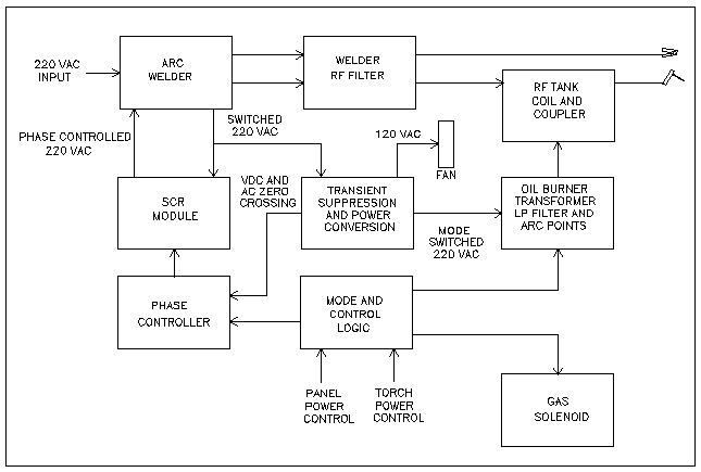
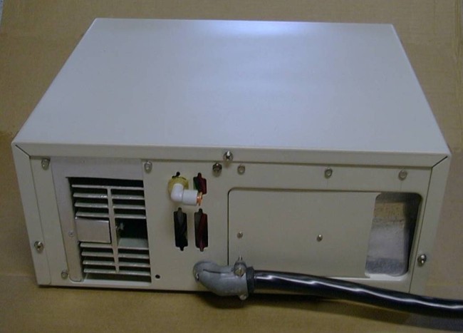
| This block diagram includes the original arc welder that is connected to
the Arcstarter and Power Control with a plug-in cable. |
| Block Diagram | Arcstarter | Power Control | Construction | Schematic Diagram | More Drawings | References | Return to Home |
|
| This block diagram includes the original arc welder that is connected to
the Arcstarter and Power Control with a plug-in cable. |
 |
 |
 |
 |
 |
 |
 |
 |
 |
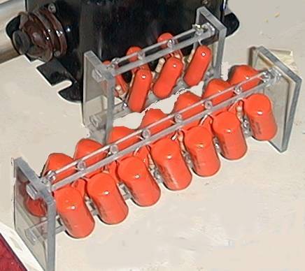 |
| The capacitor and resistor leads were twisted together and soldered, then inserted into holes in the polycarbonate housing. Epoxy glue was used to cover the soldered wires in the housing holes to prevent corona. |
 |
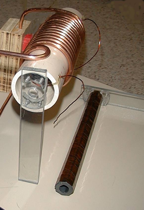 |
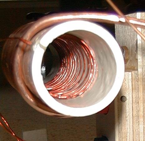
| The primary coil is wound on the inside of a pvc form. After spacing was perfect(?), the ends of the wire were epoxied in slots cut in the pvc and coil dope was applied to the windings." |
|
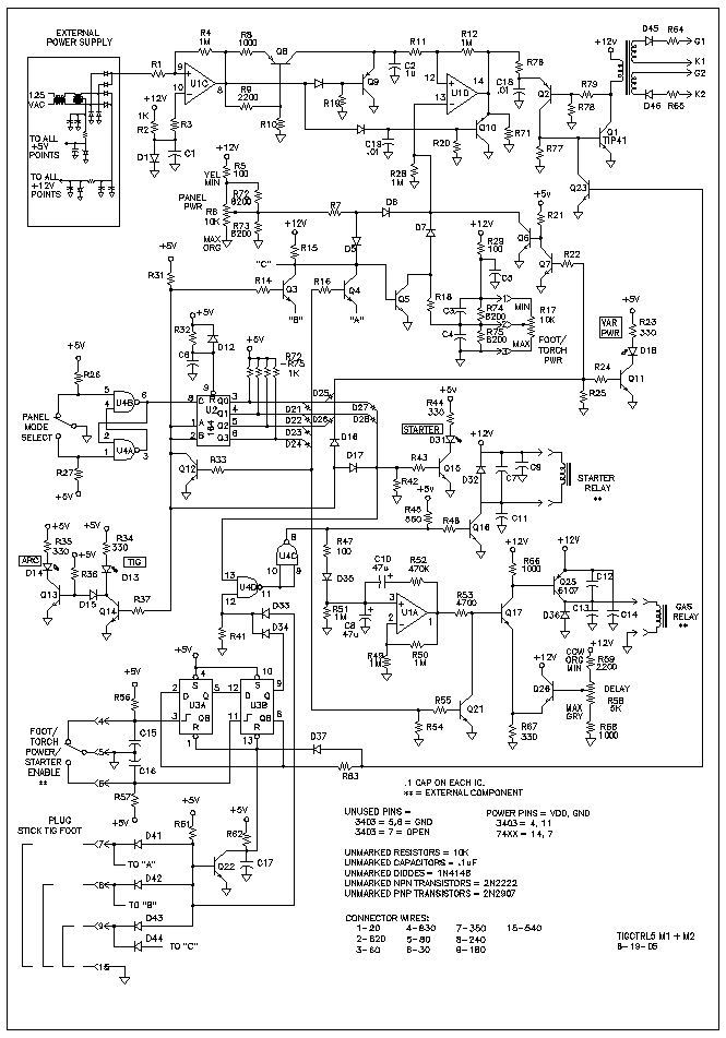
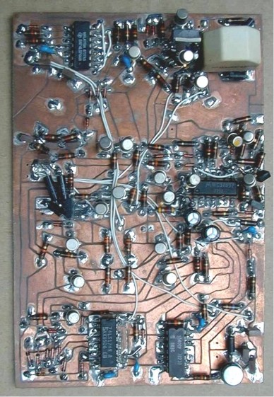
A double-sided circuit board holds the power-control and function-selector circuit. There are a lot of discrete components used in this circuit because I have them. It also made layout of the board easier. The function selection circuitry may not be to everyone's liking and could be stripped out and replaced by a rotary or other switch. I like the gas time-delay timer. It is very linear and uses a unique negative-slope linear ramp generator. But the best circuit on the board is the power-contoller. It uses a positive-slope linear ramp generator for phase timing, and the power-selection potentiometer is compensated to provide linear power selection. A simple oscillator in the gate driver gives multiple trigger pulses so the power SCRs will fire symetrically regardless of the phase lag variability due to an arcing or open-circuit welder. Some of the seemingly un-necessary components are the result of SwitcherCAD III simulations. |
| BUTTON | LED | SHIFT REGISTER | ||||||||
| TIG | STICK | PWR | START | DATA | Q0 | Q1 | Q2 | Q3 | Q4 | |
| Reset, 0 | 1 | 0 | 1 | 1 | 1 | 0 | 0 | 0 | 0 | 0 |
| Push-1 | 0 | 1 | 1 | 1 | 0 | 1 | 0 | 0 | 0 | 0 |
| Push-2 | 0 | 1 | 0 | 1 | 0 | 0 | 1 | 0 | 0 | 0 |
| Push-3 | 0 | 1 | 1 | 0 | 0 | 0 | 0 | 1 | 0 | 0 |
| Push-4 | 0 | 1 | 0 | 0 | 0 | 0 | 0 | 0 | 1 | 0 |
| Push-5 | 1 | 0 | 1 | 1 | 1 | 0 | 0 | 0 | 0 | 1 |
| BUTTON | FUNCTION | CIRCUITS ACTIVATED | ||
| GAS | STARTER | VAR. PWR. | ||
| Reset, 0 | Y | Y | Y (1) | D17, U4D, U4C, U1C, Q23, Q17, Q16, D16, Q6, Q7 |
| Push-1 | N | Y | Y (2) | D21, Q21, D27, U4D, U4C, Q16, D25, Q6, Q7 |
| Push-2 | N | Y | N | D22, Q21, D28, U4D, U4C, Q16 |
| Push-3 | N | N | Y (2) | D23, Q21, D26, Q6, Q7 |
| Push-4 | N | N | N | D24, Q21 |
| Push-5 | Y | Y | Y (1) | D17, U4D, U4C, U1C, Q23, Q17, Q16, D16, Q6, Q7 |