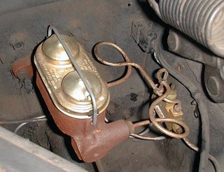
65 Mustang Dual Master Cylinder Conversion
Documentation of the switch from a single
to a dual master cylinder and replacement of the rear
brake lines. The old lines were missing and had been
replaced by the wrong parts for a dual-exhaust vehicle.
Included is a warning light and switch that warns if
there is a failure of the master cylinder balance or if
the emergency brake is left on.
I did this to my 65. It does not improve braking
efficiency or allow less pedal effort for equivalent
braking. It does provide you with some brakes should a
hose, a hard line, or a wheel cylinder spring a leak.
I used a MC from a 67 Mustang. DO NOT USE A REBUILT MC.
One, they will leak in a short time. Two, they come with
the 1/2 " shorter 67 pushrod already inserted, so
you will have to break an internal clip by pulling on the
rod. I bought a "re-manufactured" master
cylinder, before I read several forum posts warning to
use only new cylinders unless I liked replacing them. Let
me add my testimonial to the body of evidence supporting
that statement. Front-cylinder-to-rear-cylinder internal
leak after one month. To make matters worse, I, the
meticulous one who NEVER throws away a parts receipt,
couldn't find the receipt to return the MC. It is for the
best as I would probably be lured into putting another
"re-manufactured" master cylinder on just
because it was free. I do learn slow.
I bought a NEW Bendix 67 Mustang manual drum brake MC. On
the "remanufactured" MC, the pushrod was
already attached, and the pushrod on a 65 Mustang is 1/2
inch longer than the 67 rod. The 67 rod was held in place
by a clip and I had a hard time breaking that clip by
pulling on the rod. Some people said it was easy, mine
wasn't. With the new Bendix MC, the pushrod was supplied
, but not inserted in the MC. So with the new MC I could
just toss the supplied pushrod and insert the original
pushrod from the 65 .
Proportioning valves and combination valves are for disk
brake cars only. Do not use one of these. A distribution
block from a dual system drum brake car is what is
needed. With that distribution block, you will get a
differential pressure valve that supplies a ground
electrical connection if there is a failure in either
system, front or rear. The differential pressure valve
from a 67 or 68 drum brake car works well.
You could skip the differential pressure valve and plumb
the front two lines through a tee to the rear MC port and
the rear line directly to the front MC port. I used a
differential pressure valve so I could wire up a brake
defect warning light and alarm.
The rear line on a 65 Mustang ends at the distribution
block with a 3/16 flare fitting. The distribution block
used a 5/16. Check ahead of time so you don't have to
wait a day to get an adapter, Don't believe the parts guy
when he tells you they don't make such an adapter when
what he really means is he doesn't stock one.
I put a 65 mustang, factory-dual-exhaust, rear brake line
in the Frankenstang. I wanted to put it in the location
the engineers intended, but this wasn't as easy as I had
hoped. The car had dual exhaust, but they were not
original and were not installed in the correct location.
The old brake line was wired on to clear the pipes and
there was no rear body bracket for a hardline. Where does
the bracket go that is supposed to secure the rear of the
brake line to the car body?
Look from the rear, with the driveshaft tunnel at the
right, on the left section of the floor pan, where it
goes up to clear the axle.
On the vertical suface, going left from the tunnel there
is a 1-1/2 inch wide by 4 inch high reinforcement plate.
A bolt through this plate holds the muffler hanger. Two
and 3/4 inches to the left of the plate are two holes,
one above the other. The upper hole is used to secure the
rear seat on the other side of the pan. A brake bracket
at this location would be directly across from the brake
hose brass block where the hard lines are connected. Four
inches to the left of the two holes is a vertical line
stamped in the metal that I have been told was used by
Ford to locate the bracket. When the bracket's left edge
is against the vertical line the hose will attach to the
body at a point left of the axle tube brass block and
will clear the exhaust pipes as designed.
Make sure that brake hose is one for a factory dual
exhaust. It is longer and has a bracket attached to the
brass block.
It is very simple to put in a warning
light that warns if there is a failure of the master
cylinder balance. The same circuit can provide a warning
if the emergency brake is left on by the addition of a
single switch.
I received a question about the second timer in the circuit. The first timer turns the alarm buzzer on for a 2-second alarm when triggered by a negative pulse at threshold pin 6 . As a self-test, timer number two provides the trigger pulse when the ignition is first turned on. After the self-test, the alarm is triggered by a ground from either the differential pressure valve or the emergency brake switch.
I uses a pre-assembled oscillator module as my buzzer. The oscillator circuit in the lower-righthand corner of the diagram was my original planned circuit to drive a small speaker.
Like most of my projects, I built the circuit on a
circuit board and surface mounted the components. The
switch for the emergency brake is a micro switch mounted
in a clamping bracket that gives me the ability to adjust
the switch point. The pressure differential valve must be
bled to center the switch to the off position. This is
done by opening the front or back port to allow leakage
under pressure until the switch goes on. Then the port is
tightened and the opposite port is opened until the
switch goes off.
Copyright Dale Thompson.
Last revised: October 1, 2006.

