There are three sub-systems making up the control system: fill, temperature, and pump. The fill sub-system uses three solid-state water-level sensors, a mechanical water-level-switch, two solenoid water valves and a backflow preventer valve. The temperature sub-system uses a programmable temperature controller, a thermocouple, an over-temperature logic switch, an over-temperature power switch, an in-line 4500 watt heater, and a solid state control relay. The pump sub-system uses a solid-state, water-level sensor and a relay.
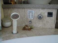
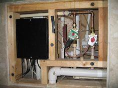
A main-power push-pull switch on the tub skirt turns on 120 vac input power. The switch is physically located in the heater control box. The 120 vac power comes from a GFI device located in a box. next to the heater control box. When turned on, 120 vac is made available to the heater interlock relay and the tub logic controller. The tub logic controller contains the logic circuits to perform the system functions according to rules governing input requests, sequence of functions, and current system state.\par \par Three primary decisions must be made and inputted before the system is initiated: to fill or not fill, to run the pump or not to run the pump, to heat the water or not to heat the water. These decisions are inputted by pressing membrane switches on the side of the sink counter support. When the decisions are inputted, the tub logic controller begins.
Selection of fill seems unnecessary, but it is needed so fill can be shut off at a lower level than selected by the manual water level switch. Normally, fill turns on the water source solenoid valves and filling proceeds until water reaches the water-level-select switch level or the maximum level detected by the solid-state water-level sensor.
The manual water-level-select switch is a diaphragm pressure switch with a knob that can select a switch point for water level from above the jets to just below overflow. The maximum level sensor is a solid-state water-level sensor that switches when its electrode contacts water. The maximum level sensor is set at a fixed height.
When water rises above the tub suction opening, water is above the heater element. At this point, the heater could be turned on if heat is selected. But other conditions must be present or the heater would burn up. When the heater is on, water must be flowing past the element to keep it cooled. This can be either filling water or pumped water. Since there is not yet enough water to turn on the pump, but the tub is being filled, it is safe to turn on the heater. A solid-state water-level sensor detects the safe water level. Another logic signal from the temperature controller in the sink counter support indicates whether the water temperature is above or below the desired temperature. If heat is desired, a 5vdc logic signal is sent from the tub logic controller to the heater control box. There a solid-state relay turns on 240 vac power to the heater element in the in-line heater module.
The 240 vac from the house circuit breaker goes to a GFI device in a box behind the tub skirt. From the GFI device it goes to an interlock relay in the heater control box. This relay ensures complete system shut down when the 120 vac power is turned off, whether intentionally, or due to a fault in the 120 vac supply. The 240 vac from the interlock relay goes to a solid state relay that is controlled by a logic signal from the tub logic controller.\par \par The last control sub-system is the pump. When water level goes above the jets the pump can turn on. As water rises to about one inch below the jets, an electrode of a dual electrode solid-state ,water-level sensor arms the solid-state ,water-level sensor. When water is about one inch above the jets the second electrode triggers the solid-state ,water-level sensor and the pump is turned on. The arm-and-trigger scenario prevents the pump from cycling on and off as the water level drops slightly when the pump begins operating.
Any operation decision (pump / fill / heat) can be changed at any time in the tub operation without problems. The system can be stopped at any point by pressing the reset buttom on the sink counter support.
TUB LOGIC CONTROLLER
LOGIC SECTION
See PL2, PL3, U11, U12, and U13 in The top center of the schematic diagram.
There are three logic outputs from six logic inputs:
Outputs:
FILL = Enables water fill solenoid
HEAT = Enables heater relay
PUMP = Enables pump relay
Inputs:
A = FILL SWITCH, Fill desired
B = HEAT SWITCH, Heat desired
C = PUMP SWITCH, Pump desired
D = DRAIN SENSOR, Water level above heater
E = JET SENSOR, Water level above jets
F = MAXIMUM LEVEL SENSOR, Water level just below overflow pipe
G = MANUAL WATER LEVEL SWITCH, Water level at setpoint
H = HEATER LIMIT SWITCH, Temperature of heater case above maximum
I = TEMPERATURE AT SETPOINT, Temperature of pump output at setpoint\par
The logic output is shown in the following truth table:
INPUTS
|
OUTPUTS
|
A
|
B
|
C
|
D
|
E
|
F
|
G
|
H
|
I
|
FILL
|
HEAT
|
PUMP
|
1
|
X
|
X
|
X
|
X
|
0
|
0
|
X
|
X
|
1
|
0
|
0
|
1
|
1
|
0
|
1
|
X
|
0
|
0
|
0
|
0
|
1
|
1
|
0
|
1
|
1
|
1
|
1
|
1
|
0
|
0
|
0
|
0
|
1
|
1
|
1
|
X
|
1
|
1
|
X
|
1
|
X
|
X
|
0
|
0
|
0
|
1
|
1
|
X
|
X
|
1
|
X
|
1
|
X
|
X
|
X
|
X
|
0
|
0
|
1
|
1= YES, 0= NO, X=DON’T CARE
SWITCH LATCH SECTION
See PL1 in the left half of the schematic diagram.
There are three identical switch latch circuits. The heat switch circuit is shown. A high reset signal at U3C-10 sets both U1A-3 and U1A-6 low, a non-latch position. Neither YES nor NO is selected. A repeating pulse from 555 oscillator pin 3 to U8A-2 causes both red and green LED driver transistors to switch on and off. When either U1A-1 or U1A-5 is grounded, the output of the associated gate goes high and through the U3 OR gate and the opposing NAND gate, latches in the high state. The latched NAND gate, e.g. U1A-3, through U3D and U6A disables U8A and stops the red and green LED flashing. The output of the latched NAND gate, through U7A or U7B, turns on the red or the green LED according to whether YES or NO was selected. If YES was selected, the output of U7B-6 supplies a high logic signal to the logic section. Each of the latch switch circuits supplies a logic signal after selection which are summed by U10A, U8D, and U10B to indicate that all three selections have been made.
U2C and U2D form a reset latch. When power is first applied, or power is lost and re-applied, the diode/resistor/capacitor network on U2C-9 causes U2C-8 to go high and reset all the latches to a non-select condition. A momentary connection of U2C-10 to the RC string on U2C-8 sets the latch and removes the reset signal.
SOLID-STATE , WATER-LEVEL SENSORS AND WATER-LEVEL-SENSOR MODULE
The three solid-state, water-level sensors are on separate circuit boards that are mounted together on an aluminum substrate attached to a section of pvc fittings and pipe. The pvc fittings also contain a closed chamber that supplies the calibrated pressure to switch the mechanical diaphragm water level switch. These components comprise the water-level-sensor module.
Stainless steel screws at points on a vertical pipe section are the electrodes for the solid-state ,water-level sensors. As water rises in the tub, it also rises in the pvc pipe and contacts the electrodes activating the sensor attached to the particular electrode.
The basic sensing circuit is used in all the solid-state ,water-level sensors. A 12 vac potential is applied to the electrodes. Alternating current is used to prevent electrode erosion. But, because ac is used, and a transistor is used as the current sensor, the transistor output is a half-wave rectified voltage. This varying voltage must be totally filtered and smoothed to a dc logic signal for the tub logic controller.
DRAIN SENSOR
See figure H2OSENS9 11-17-01.
When electrodes are out of the water, Q1-B is at VE , Q1 is off, C2 does not charge, Q2 is off, and Vout is high.
When electrodes are in water with a resistance less than 100 kilohms, Q1-B is pulled below Q1-E, Q1 turns on and charges C2 in 60 Hz pulses. C2 charges high enough to keep Q2 turned on with current through a 51 kilohm base resistor. Q2-C supplies a ground to the logic gate in the tub logic controller.
JET SENSOR
See figure H2OSENS11 11-17-01.
This sensor has two electrode sets. One set arms the sensor; the other triggers the logic level switch.
When electrodes are out of the water, Q4-B is at VE , Q4 is off, C2 does not charge, Q1 is off, Vout is high from a 10 kilohm source resistor in the tub logic controller, and Q2 in turned on by current through R4.
When the lower arming electrodes are in water with a resistance less than 100 kilohms, Q4-B is pulled below Q4-E, Q4 turns on and charges C2 in 60 Hz pulses. C2 charges high enough to keep Q1 turned on with current through base resistors. However, because Q2 is turned on, current through R3 is shorted to ground and cannot turn on Q1. When the trigger electrodes are in water with a resistance less than 100 kilohms, Q3-B is pulled below Q3-E, Q3 turns on and applies a pulse through R1 to Q1-B. Q1 turns on pulling Q2-B to ground and removing the short from R3. Current from C2 flows through R3 and R2 to keep Q1 turned on. Q1-C supplies a ground to the logic gate in the tub logic controller.
The Q3 trigger transistor state is immaterial at this point. Q1 will remain on until Q4 is turned off when the arming electrodes are removed from water.
MAXIMUM LEVEL SENSOR
See figure H2OSEN12 11-17-01.
Q3 is a rectifier that supplies current to Q1-B. Q3 will only supply current when both legs of the ac souce are present. This is a failsafe circuit to produce a water-at-maximum-level logic output if the ac voltage is lost. Q3 is turned on whenever both legs of the the ac voltage are present by a rectified voltage from the diode-capacitor pair on the base of Q3. The 15 uF capacitor on Q3-C charges and supplies Q1-B drive current through a 47 kilohm resistor. When electrodes are out of the water, Q4-B is at VE , Q4 is off, C2 does not charge, Q2 is off, Q1 is on and supplies a ground to the logic gate in the tub logic controller. Vout is low.\par \par When electrodes are in water with a resistance less than 100 kilohms, Q4-B is pulled below Q4-E, Q4 turns on and charges C2 in 60 Hz pulses. C2 charges high enough to keep Q2 turned on with current through a 47 kilohm base resistor. Q2-C pulls Q1-B low and Q1- C goes high.
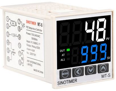
TEMPERATURE CONTROLLER
Compact DIN 1/16, 48x48mm, J-type thermocouple, relay output Farenhiet temperature display,and 125 Vac powered.
The Toho TTM-104 controller I used for many years had a catastopic failure and I replaced it with a Sinotimer MT-S from China. Although the Chinese make very good products, buyer beware. There are many factory rejects that are not repaired or destroyed, but instead end up sold for very low prices to suckers like me looking for bargains.
Without going into too much detail, it turned out I ordered two Sinotimer MT-S controllers, one from Amazon and one from AliExpress. They arrived about two days apart and I requested return of the Amazon order. The request was accepted and I was told to keep the controller. As I now know, both were rejects. The AliExpress controller worked for 10 times then failed to turn power to the heater off. The Amazon controller was bad out of the box, never turned on power to the heater.
So, to use these reject controllers, I connected the heater activation line to the alarm output and set the alarm parameter to activate the alarm for deviations below the setpoint. Thus the controller operates as a simple ON/Off thermostat instead of a PID controller. This would not be desireable for many situations, but is tolerable for a system that has 50 gallons of water, a small heater, and a high pump flowrate.
For product datasheet and setup instructions click
here.