PWM Conroller For American Flyer Model Trains


General


Recently I had a transformer for my American Flyer train burn out due to a short circuit on the track. It really fried the transformer.  It smoked and tar from the transformer made a mess on the carpet.  So it's not a repairable transformer. I wanted to make a replacement controller for two trains that I have so that their controls would be identical and my grandkids could operate them without having to relearn one versus the other.

American Flyer trains require a controller that supplies 16 Volts AC at 40 Watts or about 2.5 Amperes.  I wanted the controller to be able to reverse the direction of the train and to do this I would need to have it run on DC. 
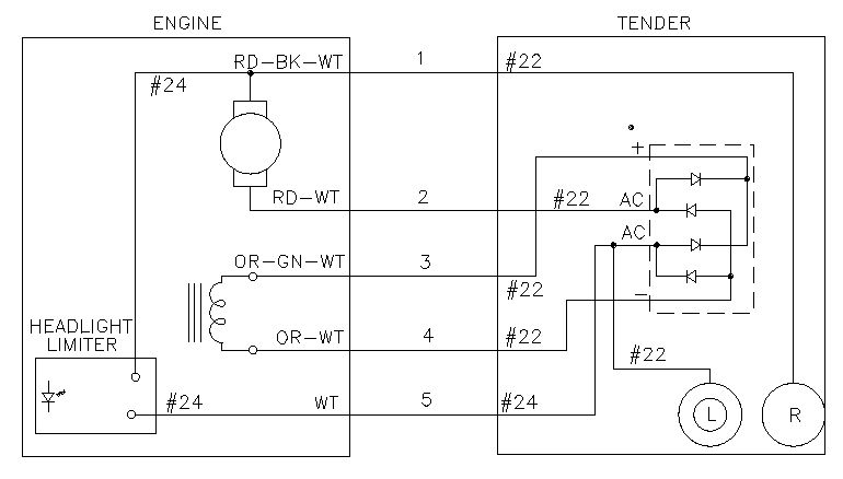
The original controller was an AC controller with a universal motor. The engines require a modification to run on DC. This mod is simply the addition of a full wave rectifier to keep the field polarity constant while armature polarity is reversing to go forward or backwards.

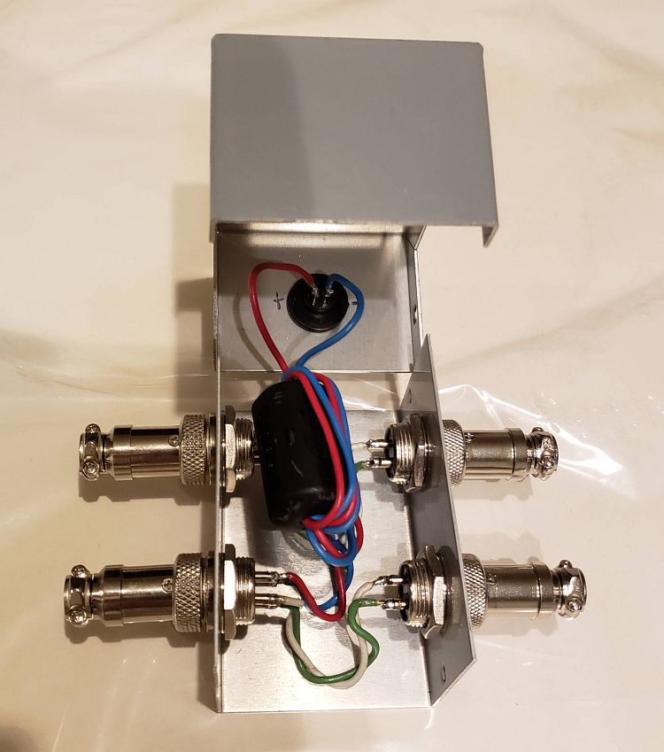
I used a 25-A high-current full wave bridge rectifier with a metal shell because I didn't want to have a big heatsink.  The metal shell allowed it to safely dissipate a lot of heat. After a lot of thought I settled on putting the rectifier in the tender. One of my trains has the reversing relay in the tender, So disconnecting the relay and adding the rectifier was easy. My older unit has the reversing relay in the engine. I could have mounted the rectifier in the engine, but I chose to leave the old relay undisturbed and make both units the same by putting the rectifier in the tender.

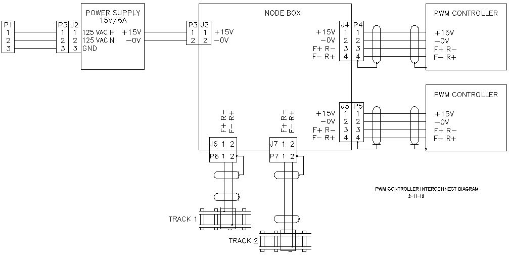
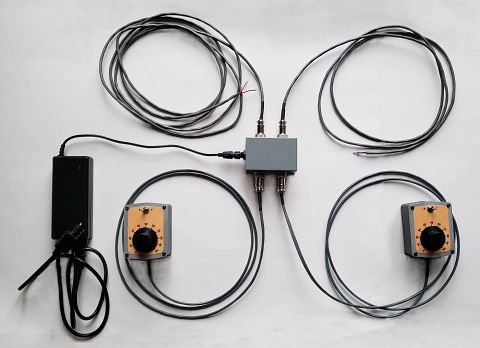
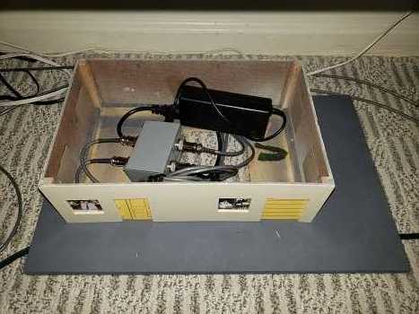
I bought a power supply rather than make one myself because it was only $9, which was almost my cost of the parts to build one, and, because my existing transformers were either too high or too low voltage, or the current rating was too low.  The power supply I bought can handle 6-amps, enough for two trains, and was 15 volts.

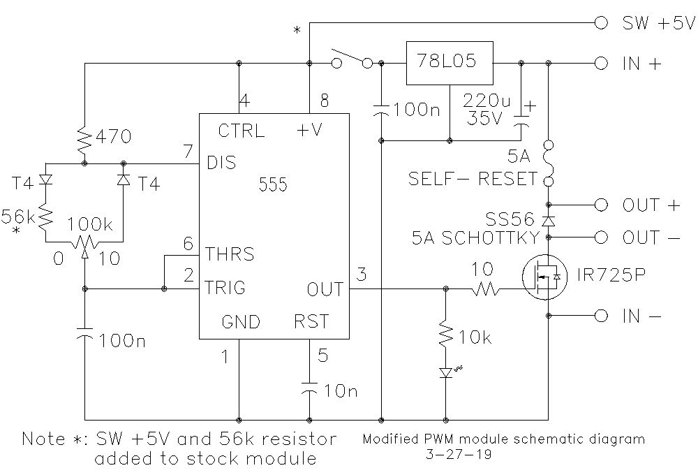
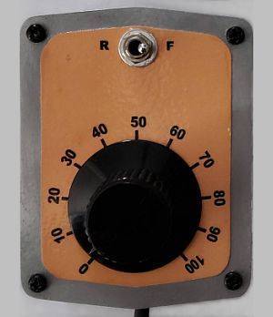
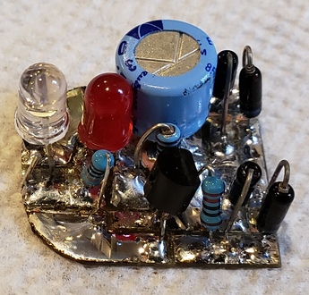
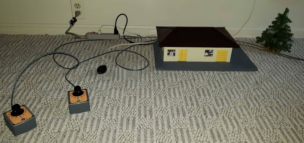
So then I needed a controller.  I decided to use pulse-width-modulated controllers to get by without large heatsinks. They were also very cheap on eBay, $1.50 a piece. 
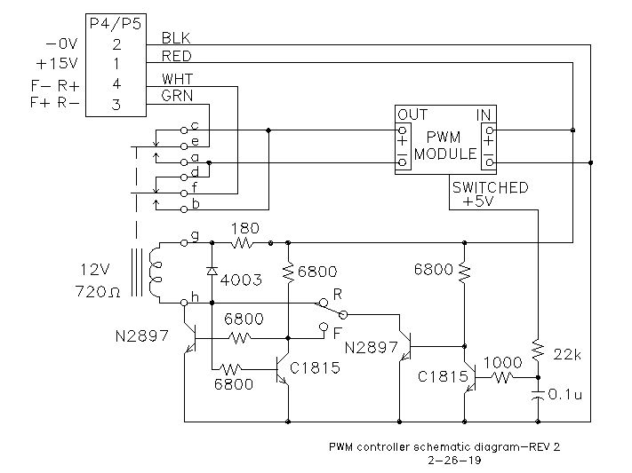
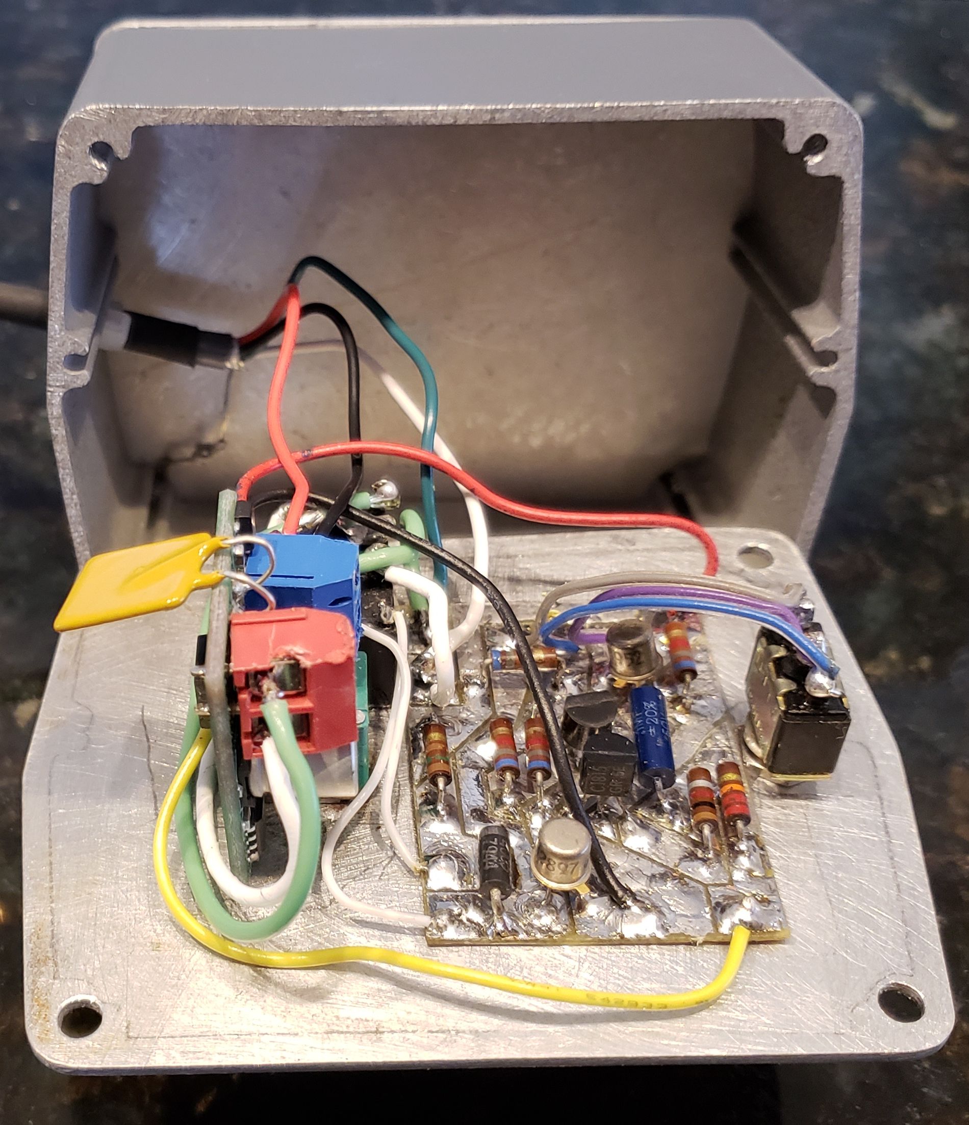
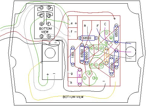
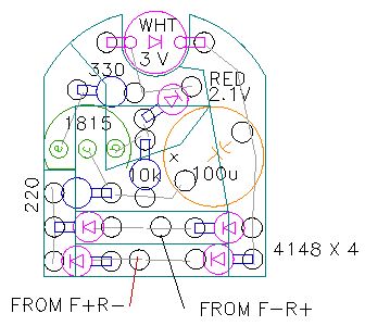
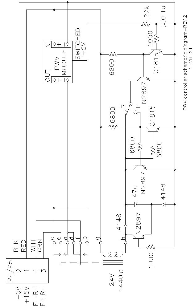
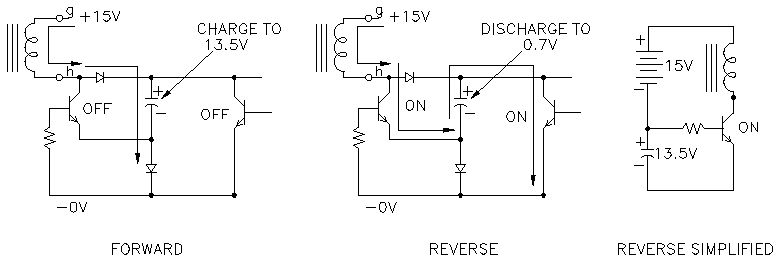
As I previously discussed, I also needed a way to reverse the trains. I did this by putting a full wave bridge rectifier on the field winding of each engine so that could be reversed by using a DC Supply and reversing the polarity on the tracks. The controller reverses the track voltage using a single pole switch that activates a DPDT relay. To go forward or reverse without damaging the engine this relay must only do its switching with no voltage on the track. I have used a relay and a few transistors to switch only when there's no voltage on either rail.  The requirement for switching with no voltage on the rail is that if the trains are going fairly fast, and then, the controller is switched from say forward to reverse, the voltage across the motor and the current throught the motor is doubled because the motor is rotating at speed and the generated back-EMF added to the  controller voltage exceeds the motor maximum voltage.

The real reason for the relay is to prevent a button pushing 2-year-old boy from flipping the forward-reverse toggle switch repeatedly because it is there.


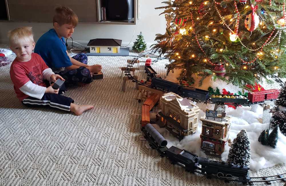
PWM Controllers in Action Christmas 2019


Basic Circuit

Layout Requirements:


Easy to build
All circuitry must fit in hand held boxes and remote power box.
Must be useable by 8 year old.

Circuit

The Pulse-Width Modulated (PWM ) controller module is a simple 555 timer in an asable oscillator configuration. The oscilator drives a power FET to provide pulsed DC to the train motor. I made two modifications to the controller module. First, I soldered a wire to the switched +5V side of the on-off switch to provide a control signal to the forward-reverse switching circuit. Second, I inserted a 56-kilohm resistor between the charging diode and the potentiometer. The resistor causes the initial pulse width after switch turn-on to be 30-percent which is approximately 5.5V. The resistor theoretically lowers the pulse frequency from 13550 Hz To 7962 Hz. The advertised frequency of 10000 Hz is unlikely and the calculated 7962 Hz should be unnoticed. If you are using a can motor, you may choose to leave this resistor mod out as the initial voltage would then be near 0V.

The rest of the circuitry is the logic to prevent changing train direction without the train coming to a complete stop. The circuit is simple and explanations are readily available on many webpages, therefore, I will not describe its operation unless I get requested to do so. I will note that the component values shown are not very critical. for instance the 2N2897 was selected because I have a bunch of them, as was the 2SC1815. Same with the resistors, but keep the 6800-ohm resistors below 9100 ohms. The 1000 ohm resistor and 0.1uf capacitor were part of rev. 1.5a and are probably not needed, but it was easier for me to leave them in than to take them out.


PWM Controller
Interconnect Diagram


PWM Controller
Schematic Diagram


PWM Module
Schematic Diagram


Node Box
Schematic Diagram


Construction

Parts List

It seems like everything comes from eBay nowadays, and most of the parts that I picked came from eBay.

Item Part Number Source Cost Comment
2-pin connector set for Node box to track cables GX16 Ebay $1.87for 2pc
4-pin connector set for Controller to Node box cables GX16 Ebay $1.93for 2pc
2-pin plug for power supply to Node box cable Conxall 17282-2PG-300 On Hand $0.00
Power Supply 15V 6A laptop supply Ebay $8.93
PWM Module 3V-35V 5A Motor PWM Speed Switch Ebay $2.82 for 2pc
DPDT 12Vcoil 2A contacts relay HK19F-DC12V-SHG Ebay $0.80 for 2pc2pc used of 10pc purchase
Node box 2"x3"x1.5" metal box On Hand $0.00
Controller box 1.5 x 2.5"x 3.5" metal box On Hand $0.00Constructed
Dial Plate Laser Printed On Hand $0.00Constructed
Total $16.35


All connectors are different to prevent incorrect connection. To prevent accidental disconnection, the power supply connector was changed to a screw lock type I had left over from a previous project.

I bought 10 direction-reversal relays, so that they would be $0.40 a piece for the two I used for the controller. The other 8 would be used on some later project. Bought in the quantity of two, the cost would be $0.94.   The relays are rated at 2A continuous, which is probably the highest current flowing during normal operation. I rarely if ever have run the trains at full speed. These relays have not worked out well.

When the controller intermittantly failed to work in reverse, I spent an hour of troubleshooting the circuit and found that the relay was defective. So, I guess the true price was $0.90 for 2pc. Lesson learned: always test parts fron E-bay before using. But wait, there is more. After the first real useage by my two test engineers shown in the first photo above, another relay failed. Was it that a two ampere relay was not large enough? After careful disassembly of the failed relay I found deformed and discolored switch contacts. It appears that the bifurcated contacts were not aligned and only one of two on each switch ever made contact. There is no manufactures' marking on these relays and I believe they are rejected parts sold as full-spec equivalents. I think future failures are imminent and will have good relays ready for next year. See the addendum at the end of this webpage.

The 1-1/2 x 2-1/2 x 3'-1/2 controller box was constructed from available metal.

The knobs are large and taken from some scrap piece of equipment. Large kobs were needed because kids have small hands and large knobs are easier for them to handle.The dial plate was made using photo paper in a laser printer and coating it with clear laquer.   In the past I have used everything from push on labels to India ink lettering. For awhile, I considered using a laser printed negative dial plate and ironing it on the painted box case, much like I use for making printed circuit boards. But instead, this time I decided to use a technique I applied to sucessfully duplicate a nameplate for an antique Eureka telephone.   

The dial plate was drawn to scale using my DesignCAD program, then an image file was exported. The image file was loaded into Irfanview, an image manipulation program. In Irfanview, the white background color was swaped for the color that I wanted. Further manipulation in Irfanview allowed me to size the dial plate, duplicate the dial plate, and print 9 copies on a single sheet for photo paper.


Construction Details

Construction is very simple and straightforward. The photos below just reflect the way I did it.


Inside Node box


Inside Controllers


Controller Internal Wiring


Controller Board Etch Pattern


Controller Front Panel


Components Connected


The Train Modification

The train mod consists of disconnecting the forward/reverse relay, located in the locomotive tender of the model 307 and in the engine of the model 350, and adding a bridge rectifier in the tenders. I then connected the the field winding to the bridge rectifier and connected a LED headlight circuit board. The LED headlight board replaces the standard light bulb and has a current limiting circuit to keep the LED at a fairly constant brightness at all operating train speeds.


Engine-Tender Modification
Schematic diagram


Headlight Limiter Schematic Diagram


Headlight Limiter Layout Diagram


Headlight Limiter
Board-Cut Diagram


The Headlight Limiter Board relaces the light bulb. The board is shown below without the metal clip that was fabricated to align the LED with the headlight lense. The board shown also has the LED aimed in the opposite direction of the final version. I often use an Xacto knife with a mofified blade as a chisel to cut very simple PC-boards instead of etching them as I did with the controller boards. The ground and honed blade shown below cuts a nice 20-mil groove through the copper layer.


Early LED Current-Limiter Board
Before White LED Was Reversed


Chisel From Xacto Knife Blade


Performance

The forward-reverse relay worked as expected. Voltage polarity cannot be changed until the speed control is turned to 0 (off).

The original motor in the American Flyer 307 Reading Atlantic 4-4-2, which is designed to operate with voltage from 7 to 16 volts, starts to crawl at 20 on the new controller.

The original motor in the American Flyer 350 Royal Blue 4-6-2, which is designed to operate with voltage from 7 to 16 volts, starts to crawl at 20 on the new controller.

There was no audio noise detected from the controllers or trains.


Train Station to Hide Peripherals

My dad started building a train station for me about 60 years ago but never finished it. I have used it in my Christmas setup as it was built, but decided to spruce it up to hold the power supply and the wiring node box. I also modified a 4-outlet power strip to provide two remotely switched outlets for the train power supply and a LED indicator to remind me to turn off the power when done playing. The power strip modification consists of cutting one brass contact strip and connecting a pendant cable with a switch on the end. The LED indicator is a 25-kilohm resistor in series with a 1N4007 diode and a red LED.


Train Station Used to Hold Controller Peripherals


60-year-old train station started by my dad but never finished


Same station used to hide controller components


Modified power strip with two switched outlets

Relay Change

After two relay failures due to, I believe, rejects passed on as good parts, I decided to be prepared for replacement relays upon the next failure. The original 12V coil, 2A contact relays should have been adequate, and had a low current requirement due to their 720 ohm coil. I did not want to significantly increase the power to drive the relay, but wanted to increase the contact current rating. I found a 24V coil, 8 A contact relay with a 1440 ohm coil resistance and decided to use it. With the 12V relay I was wasting 46mW in a resistor to drop my 15V power supply to 12V. By using a capacitor pull-in circuit I could actually decrease the power needed for the relay. After a 25 ms pull-in period, the 24V relay only draws 10mA from the 15V supply.

I built and tested two relay pulser boards to have them ready to install when or if another 12V relay failed.

Well it happened. Another relay failed. So here is the new version.


Relay-Pulser Pattern


Pulser Inside Controllers


Controller Internal Wiring With Added Pulser


PWM Controller with 24V relay
Schematic Diagram


The additional transistor, diodes, and resistor form a relay pull-in voltage pulser that raises the voltage across the relay to 28.5 volts for about 25ms.

With the F/R direction switch in the forward position, the 47uF capacitor is charged to 13.5V by current from the power supply +15V terminal through the relay, a 1N4148 diode, the 47uF capacitor, and another 1N4148 diode to the power supply 0V terminal.

With the F/R direction switch in the reverse position, current flows from the power supply +15V terminal through the relay and a turned-on 2N2897 transistor to the negative terminal of the 47uF capacitor. The capacitor voltage is added to the power supply 15V. The current from the 15V power supply and the 13.5V capacitor charge (28.5V total) continues trom the capacitor positive terminal to through a second 2N2897 transistor to the negative power supply terminal.

The result is an initial pulse of 28V accross the relay, followed by a continuous holding voltage accross the relay of 15V.


Relay Pulser Circuit
Simplified Schematic Diagram


Copyright Dale Thompson,
23 January 2019 through
last revision on 29 January 2021