Cleaning And Timing An Automatic Electric Dial
General
The Automatic Electric type 24 dial in my Strowger PAX L427A was so dirty it would not rotate.
The best solution was to send it to
Steve Hilsz and have it cleaned correctly and timed perfectly. He only charges $6.00. But I just got a dial back from him and I hated to spend the $13.00 in shipping to get this dial there and back. I am so cheap. If only I had had the foresight to send him both dials I wouldn't have hesitated. Anyway, this is what I did.
Cleaning
The Automatic Electric type 24 dial is very easy to dissassemble enough to clean and lube. Remove the finger wheel. Remove the number plate. That is far enough.
DANGER: ALCOHOL, XYLENE, AND NAPTHA ARE FLAMMABLE AND TOXIC. READ AND FOLLOW THE WARNINGS ON THE MANUFACTURER'S CONTAINERS.
Dip a artist's paintbrush in 90% alcohol and brush all the easy dirt away from the gears and moving parts. Be messy, use a lot of alcohol.
Rinse the dial in flowing tap water in the sink.
Blow the dial dry. This will take compressed air. Using your lungs will not suffice.
Dip the artist's paintbrush in xylene or naptha and brush dirt, disolved grease, and oil away from the gears and moving parts. Be messy again, use a lot of xylene or naptha.
Dip the artist's paintbrush in a 50%/50% mixture of alcohol and ammonia and brush the solvent residue away from the gears and moving parts. Be messy again.
Rinse the dial in flowing tap water in the sink.
Blow the dial dry. This will take compressed air. Using your lungs will not suffice.
Oiling
Use a toothpick as your oiler. You are not packing a wheel bearing, you are oiling a watch.
I use transmission fluid as a lubricant for my old clocks. That is what I used on this dial.
A drop on the end bearing point of each rotating shaft.
BE VERY CAREFUL WHEN OILING THE SHAFT-END BEARING INSIDE THE GOVENOR SHELL. A DROP OF OIL IN THE SHELL AND YOU GET TO RETURN TO STEP ONE, CLEANING.
Rub each tooth of the govenor shaft drive gear using the oil dampened toothpick (a very light oiling of the gear).
Do the same to the main drive gears on the fingerwheel side of the dial assembly, a little heavier oiling is okay here, but still be stingy.
Two drops, as you are dialing, on the center of the govenor screw shaft where it contacts the drive gear.
Finally you are at the point of oiling the fingerdial shaft. The pawl oiling is easy;oil the pawl shaft and the pawl teeth lightly as before. But it is hard to oil the main shaft without disassembly.
Set the dial on some paper towels with the contact-springs side up. Put multiple drops of oil on the end of the main shaft and on the top third of the return spring. About one third of the way from the shaft end, the shaft reduces to minimum diameter and goes into its bearing. You are trying to get some oil to work its way down the top part of the shaft and through the spring onto the shaft and down to the bearing. You don't want oil running all over your clean dial so do this patiently. Rotate the shaft occasionally, it helps the oil move.
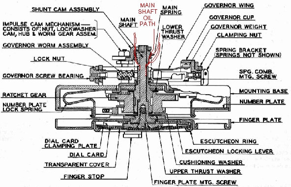
Main Shaft Oil Path
|
Timing
I thought that since the phone was likely a working phone that had been allowed to sit idle so many years it would be timed about right when it was cleaned and lubricated. Not true. The speed seemed about right and the impulse contact spacing looked pretty good. So here is what I found.
The speed was as right as I can make it. It compared well with two other phones with Automatic Electric dials, and a dialed "0" took more than 10 but less than 11 second as measured on my microwave timer ten times. I tried slowing the dial slightly and speeding the dial slightly, but that failed. Slower dial speed got me a message tone indicating my 10-digit test number took longer than allowed. Faster dial speed gave no change, a "not a working number" message.
I was left with only the make/break timing as the problem. This seemed unlikely as the cut of the cam should make this a fixed ratio if the contact gaps were properly adjusted. I read the Automatic Electric documents and checked that the gap between the impulse-contact-spring tip and the lower level of the cam was .015 inches as specified (+/- .002). I also checked that the gap between the impulse contact spring and the middle contact spring was .015 inches as specified (+/- .002) when the impulse-contact-spring tip was contacting the middle of the higher level of the cam. Everything was in spec but it didn't work. Conclusion: the spec is wrong.
I photographed the cam, traced it on my CAD system, and miked all the dimensions, then checked the points where the switching should take place for correct timing. The dial setting looked exactly right. I couldn't increase the break time, so I tried decreasing it by bending the stop spring. This made the gap between the impulse contact spring and the middle contact spring less than the specified .015 inch, but it worked. According to my drawing of the cam, the break percentage that works at my location is 50% to 54% break time.

Cam Break Points
|
Copyright Dale Thompson,
December 2, 2014 through
last revision on December 2, 2014