Western Electric 233G Payphone Restoration-Conversion
General
I bought my Western Electric 233G payphone in 1988 at Hecht's department store. The "restorer" stripped out the coin trigger switch and relay mechanism, then used the space to put in a 101A network and Automatic Electric type 46 ringer. The phone came from a military base. Its instruction plate says to make a call, deposit 10 cents, listen for a tone, then dial the number. I wanted that same sequence.
Pulse dialing worked on Comcast when I showed my grandaughter how to use a rotary dial. She was very excited, had to try it, called her Dad.
When I switched to Verizon the rotary dial did not work. I thought Verizon's equipment was not accepting pulse dialing: wrong. Verizon Maryland uses a Lucent-Alcatel 7342 0-series (0-211E) ONT box: 49.3 Vdc at idle, 5 Vdc off-hook, 26 Vdc during ringing with 54 Vac (75V peak) during ringing. The 7342 ONT documentation clearly shows it is POTS capable with rotary dialling. Perhaps Verizon had disabled that capability I thought.
After trying an old phone that had switchable pulse-DTMF dialing and having it work, I decided the problem was the dial speed. I verified this by using a new-old-stock (NOS) dial I had in my basement; it worked perfectly. So, I tried clearing the dial, as the phone-restorer had used oil on the dial gears and got it everywhere. I cleaned the gears with paint thinner and then alcohol, but the dial was still slow compared to the NOS dial. I resorted to tightening the govenor spring until it sounded the same as the NOS dial and took the same amount of time to return from a zero number dialed. Result; perfect call placement.
I decided to repackage the phone to put the 101A network and the type 46 ringer on a board in the coin box. There would also be room on the board to put a coin-detector circuit board to possibly simulate the original phone coin sequence using relays and a photo sensor.
Why not put in an original coin mechanism and modify it? I wanted the sequence to match the original plate instructions, It would cost $60 to buy the missing phone parts. Then I would have to modify the coin relay to operate on lower ring voltage (54 Vac-75Vpk) if possible. I am not sure of the Verizon box current capability, and not sure the ONT box used by Verizon now will be used in the future. Plus, I like to design small circuits.
I rewired the 233G to put the network, ringer, and coin-detector into the coin-box compartment.
The first set of diagrams shown below are of my final version that uses a simple reed switch as the coin switch. The second set of diagrams and photos are of an opto-switch, coin detector that also worked, but used more parts. I have also included diagrams further down that show my original opto-switch that I built that had no moving parts. It worked, but drew too much current.
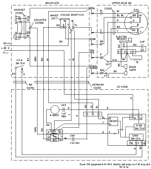
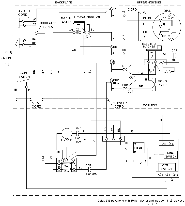
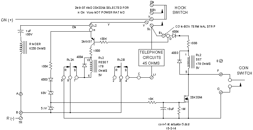
Schematic diagram of phone with magnetic-reed switch
|
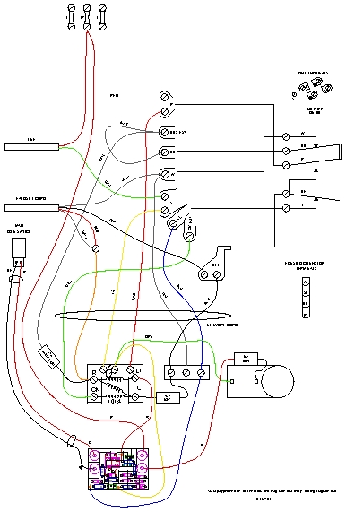
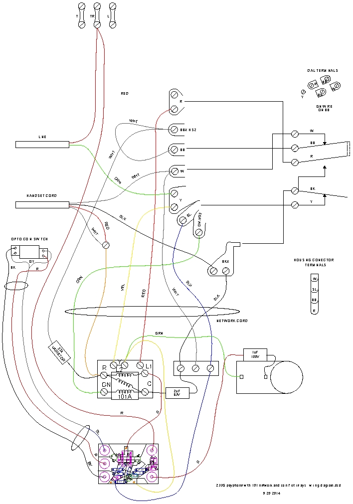
Wiring diagram of phone with magnetic-reed switch
|
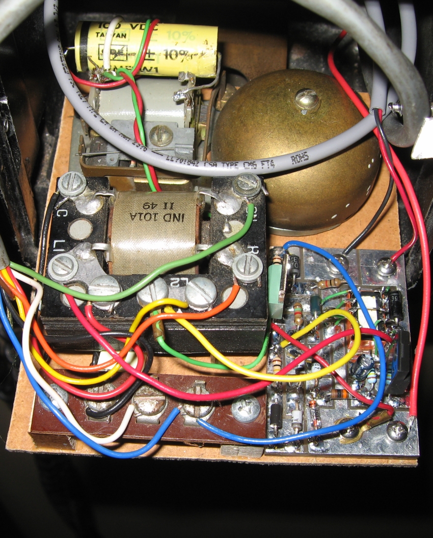
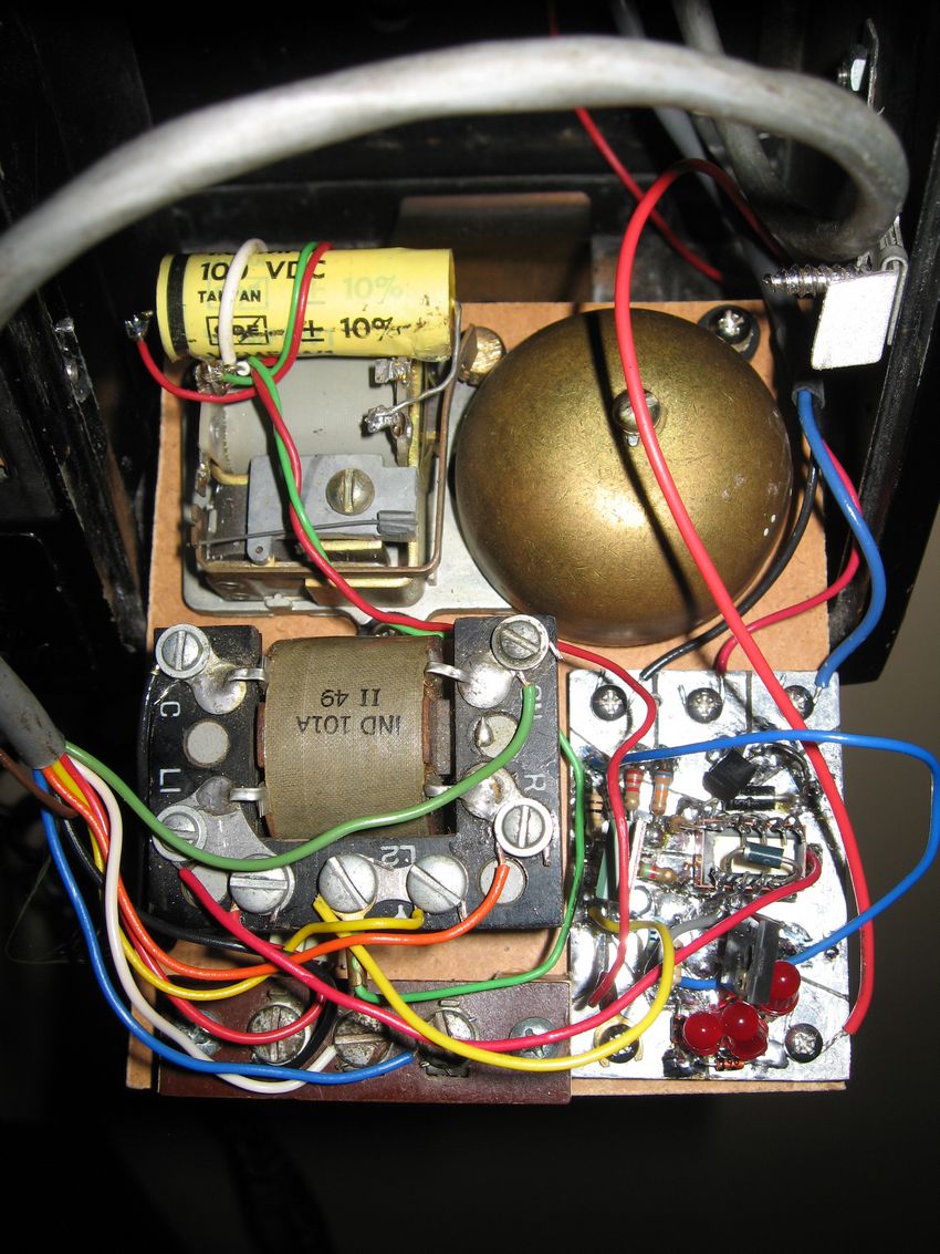
Network, ringer, and mag-switch-coin-detector mounted
on board in coin box
|

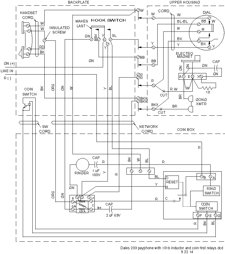
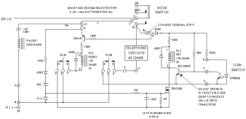
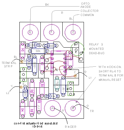
Schematic diagram of phone with opto-switch
|
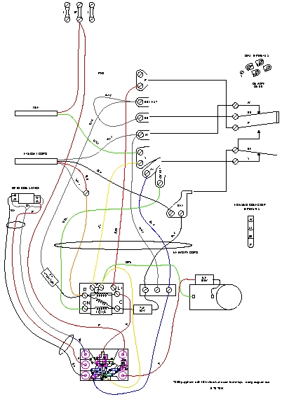
Wiring diagram of phone with opto-switch
|
Network, ringer, and opto-switch-coin-detector mounted
on board in coin box
|
The Automatic Electric type 46 ringer was wired by the "restorer" with a 1-µF capacitor. I tried a standard .47 µF, but it wouldn't work, so I retained the 1uF. I added a 2-uF capacitor to the telephone network that the restorer left out. The restorer cut the wires to the coin microphones, I left them cut.
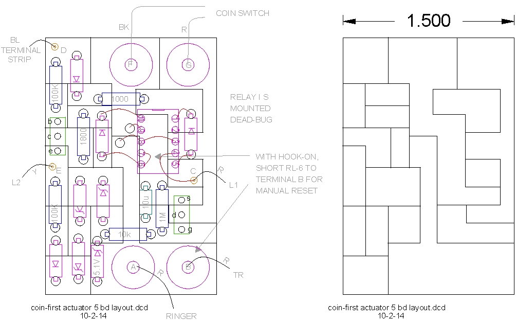
The circuit board on which I built my coin-detector has plastic stand-off strips that allow terminals to be fabricated out of board copper on on the board, with tapped threads through the board and the plastic strips. The tapped holes use brittle, hard Plexiglas and adequately hold the terminal screws. Another set of tapped holes in the plastic strips allows mounting the detector-board to the bottom-board from the bottom .
The latching relay is a NEC, EA2-5TNFG, dual-coil, latching relay bought on E-Bay for another project for about $2.50 each. Notice that it is mounted dead-bug. I was confused by the datasheet layout, and did the board layout inverted. This required me to mount the relay dead-bug and use wire to run up from board to the dead-bug. It is messy looking but works good for testing and troubleshooting, and it is also easy to solder to the short leads of the relay. It is not easy to surface-mount solder a through-hole relay; replacement of a surface-mount soldered relay is very difficult if the relay is bad. This dead-bug arrangement worked so well that I stuck with it when I laid out the second generation board.
Circuits
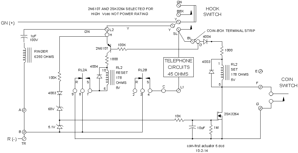
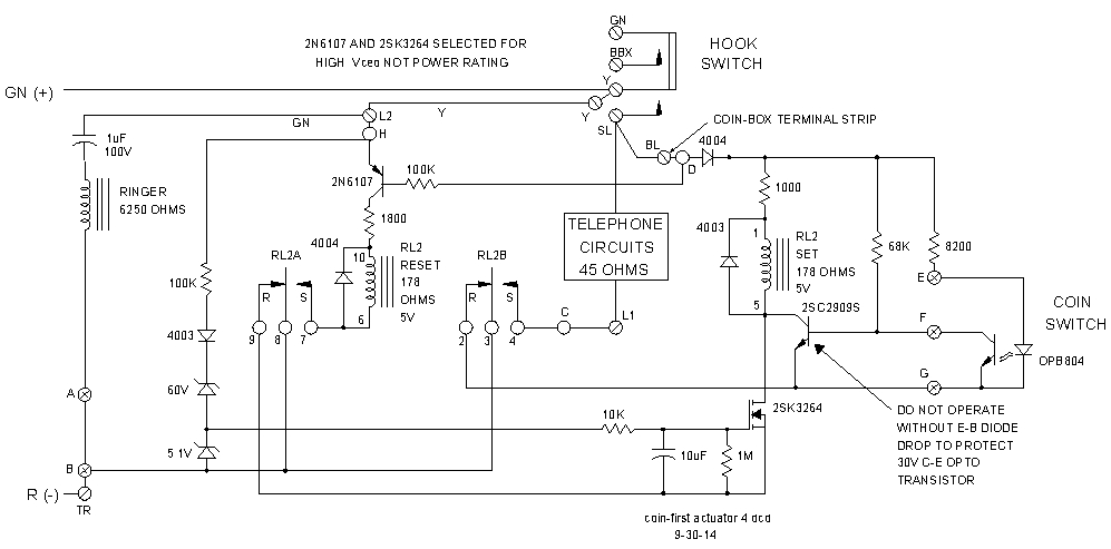
A latching relay and a homemade coin detector make up the coin-detector circuit. You may notice that one PNP transistor and a FET are power devices. This is not due to the power requirements, but is what I had available with high Vce specifications. The one transistor in the opto-switch version that is not a power transistor was selected for a high gain at a high voltage, and I had it. Old CRT monitors are a good source of high-voltage transistors. Why the need for high voltage transistors? Nasty transients every time an inductor or capacitor is switched. Telephone lines are really messy.
Another item of note: the latching relay I used will hold its set connections until the reset coil toggles the armature past the switching point. I do not know if this is true of all switching relays. If the set connections opened before the relay toggled, the relay would chatter and not switch to the reset position. I that case, it might be possible to connect the RL2-6 reset coil pin to terminal B, connect RL2-2 to terminal G, connect a 10-kilohm resistor from terminal D to terminal G, connect RL2-9 to the emitter of the 2N6107, and connect RL2-8 to the base of the 2N6107. This should allow the transistor to turn on and reset the relay then be turned off by the relay after toggling has been accomplished. I have not tested this possible fix.
Schematic diagram of magnetic-reed-switch, coin detector
|
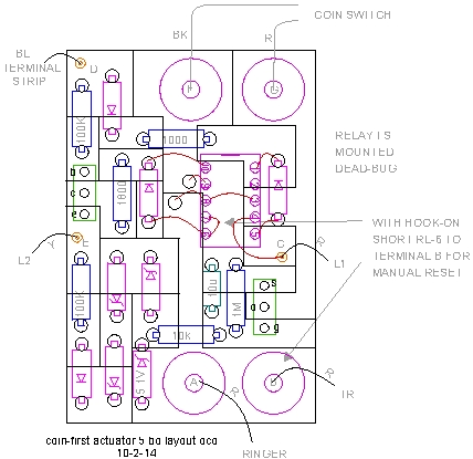
Reed-switch, coin-detector board layout
|
Schematic diagram of coin-detector
|
Coin detector board layout
|
Sequence with incoming call:
At Idle
The ringer is across line 48 Vdc.
Phone is on-hook.
Detector circuit is not connected. Sixty-volt zener diode blocks current to 2SK32629 FET.
Ringing
Ringing voltage exceeds 60V zener diode breakdown and current charges a 10 µF capacitor. A 100-kilohm resistor connected to the zener diodes, a 10-kilohm resistor, and the capacitor filter out the multiple transients that occur on the line whenever a phone is connected or disconnected.
The filter takes about one second of ringing to turn on the 2SK32629 FET that arms the detector. The detector will return to the disarmed state about 8-seconds after ringing stops due to the capacitor being discharged by a 1-megohm resistor.
Picking up receiver (off hook) connects detector
Dual-coil, latching relay RL2 is set by current through the 2SK3262 due to voltage on 10uF capacitor. The RC time constant at the FET gate will keep the FET on for 8 to 10 seconds after last ring. When RL2 is set it turns on the telephone circuits, turns off the ring detecting FET, turns off the coin detector, and connects the relay reset circuit (2N6107).
The phone is on. Between the hook switch and the detector circuit, a diode prevents circuit damage if the ring voltage is negative at the instant that the hook switch connects the line.
The line voltage drops to 5Vdc when the telephone network is connected.
Hang up
The line voltage goes from five volts to 48 volts. Transistor 2N6107 is turned on by current through the 100-kilohm resistor and the telephone circuits. RL2 is reset, the reset circuit is disconnected, the coin detector and the ring detecting FET are enabled.
Place coin call
Phone is off the hook
Detector is connected to 48 V line.
Coin-switch is active.
In the Opto circuit, the LED is running with less than 7 mA line current, which equals a on-hook to the telephone loop.
Coin drops
Coin hits balance beam.
Balance beam tips and switches the magnetic reed switch. In the Opto circuit, the balance beam tips and breaks the light beam, which turns on the 2SC2909.
Relay RL2 is set.
When RL2 is set it turns on the telephone circuits, turns off the ring detecting FET, turns off the coin detector, and connects the relay reset circuit (2N6107).
The phone is on. The line voltage drops to 5Vdc when the telephone network is connected.
Hang up
The line voltage goes from five volts to 48 volts. Transistor 2N6107 is turned on by current through the 100-kilohm resistor and the telephone circuits. RL2 is reset, the reset circuit is disconnected, the coin detector and the ring detecting FET are enabled.
Coin Switches
Magnetic-reed switch
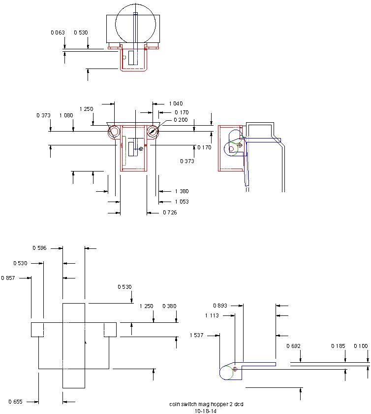
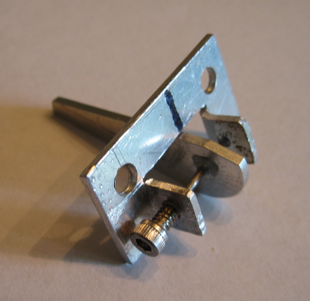
The magnetic coin switch was made from a normally open reed switch. This switch eliminated the transistor and resistor of the opto circuit and was much simpler than the opto circuit. A simple balance beam is moved by the dropping coin and a magnet on the balance beam trips the reed switch. The balance beam uses a stainless-steel, non-magnetic shaft that is sharpened on each end as an axle. The axle was sharpened by turning it in a drill press chuck and holding a grinding stone against the shaft. A dimple drilled in the aluminum switch case and another dimple drilled in a stainless-steel, non-magnetic screw serve as the bearings for the axle. Besides actuating the reed switch, the magnet provides the balance for the beam. A small piece of iron is positioned so that the magnetic attraction pulls the beam to a horizontal rest position.
Three turns of iron wire from a paper clip wrapped arround a piece of copper wire form the beam positioning ball. I moved the iron ball around the sides of the aluminum case until I found a spot where the balance beam was level. A dab of epoxy on the copper wire holds the ball in place and allows me to readjust the balls position in the future if necessary.
To mount the reed switch to the wall of the aluminum case, and be able to fine-adjust it for optimum trip point, I glued a piece of tubing to the wall as a bracket. First I found a piece of insulation that loosely fit the reed switch, and inserted the switch in the tube. After forming the leads, I put a drop of epoxy on the tube and positioned it on the wall so the center of the reed switch was nearly at the center of the magnet. A drop of finger nail polish on the tubing and the reed-switch glass holds the reed switch in its final adjustment point.
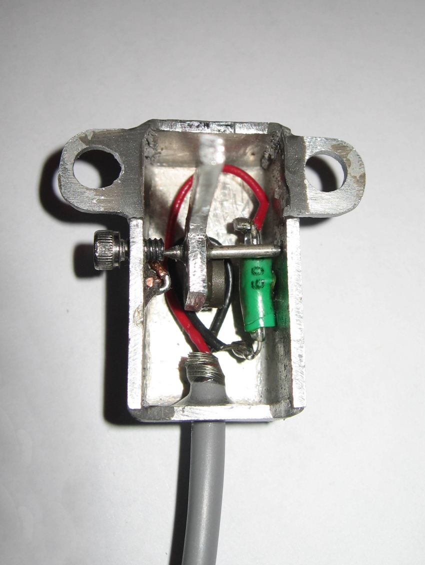
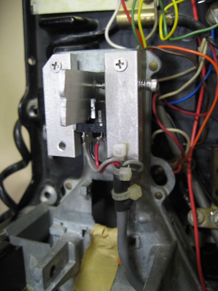
Magnetic switch inside view
|
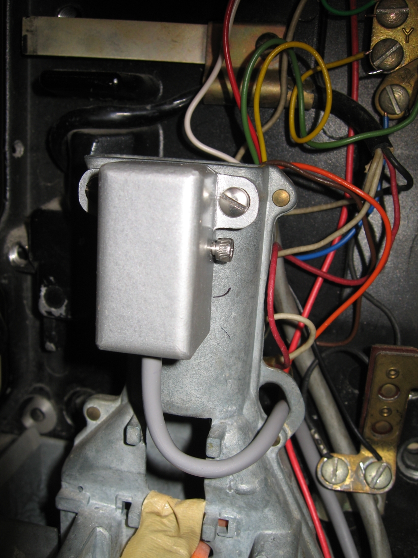
Magnetic switch mounted
|
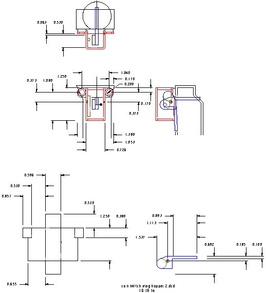
Magnetic switch dimensions
|
Switches that didn't work
Long range opto switch
This is what should happen, but doesn't
The ONT 7342 is specified to detect a off-hook condition at 20 ma. There is no minimum specification, and is appears that my ONT considers greater than 8 ma to be off hook. This makes the LED drive current an off-hook condition. Although the phone is disconnected, the ONT begins timing the connection and issues a warning tone in 15 seconds then blocks dialing a number. Everything seems fine if you pick up the receiver, deposit your coin, listen for a dial tone, and dial your number within 15 seconds. If you are slow, you have to start over. I find this unacceptable and have tried several ways to get arround the problem. Reducing the LED drive current to 5 ma and making the opto-transistor into a darlington pair looked promising, but failed in the end. Several mechanical switches were tried but also failed. I tried making a mechanical switch using a very small magnet on a balance beam and a reed switch. This worked, but getting the trigger point adjusted was just too finicy for me, so I settled on my original detector circuit with a OPB804 and a balance beam to trigger it. Eventually I returned to the magnetic reed switch and made it work.
The long-range opto coin switch was made from a OPB802 opto diode-transistor interruption detector. It was cut into two pieces. What had been a quarter-inch gap was increased to about 1 inch. Don't expect a hard turn on, just a voltage dip. A big collector resistor was needed to amplify the dip, and switch the 2SC2909 relay driver.
An aluminum band around the coin shoot held the two pieces of the OPB802. Slots in the shoot are not straight across from each other, so the pieces of the opto-coupler needed to be adjusted after the band was mounted on the shoot to get the LED beam aimed at the phototransistor. The band was cut to make tabs where the opto pieces was to be mounted so the tabs could be bent for alignment.. The opto pieces were glued on the tabs cut in the band for alignment. They were kept as parallel as could be done by eyeball. The opto-coupler pieces could be taken apart to remove the LED and the phototransistor. The housing of the pieces were glued so replacement was possible without readjusting the alignment tabs.
When the band was mounted and the board connected, The one-kilohm resistor was unsoldered from the relay so it was not operating, and then the tabs were bent to get to the lowest voltage on the opto collector when the shoot was unblocked.
Care was taken to not operate the opto-coupler without the 2SC2909 in place as its base-to emitter diode protected the low Vceo phototransistor from destruction.
This switch worked great, but drew 20 ma of current and the ONT thought the hook was off. All attempts to operate the LED at 5 ma failed, including using the phototransistor as a darlington pair and realigning the light beam to peak output using a a meter instead of by eyeball.

Long_range_opto coin switch
|
Opto switch
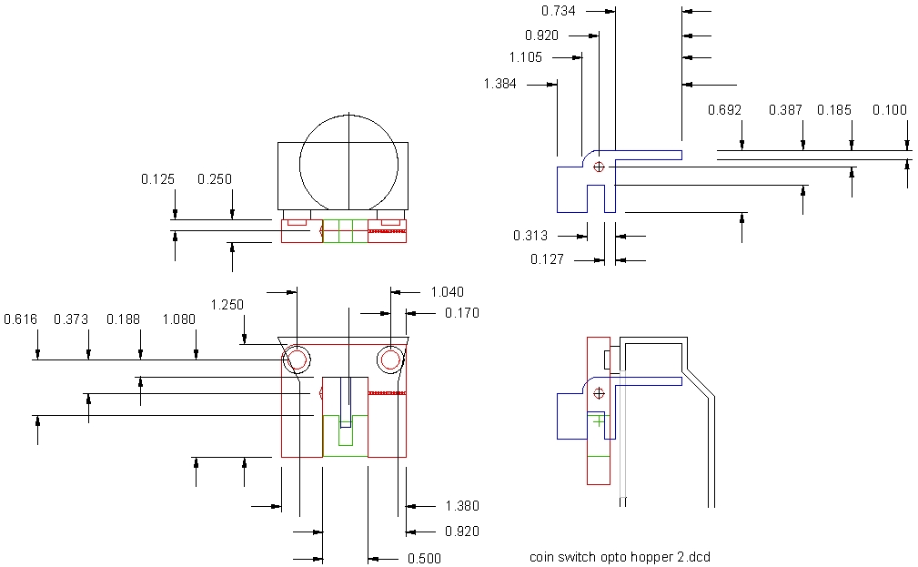
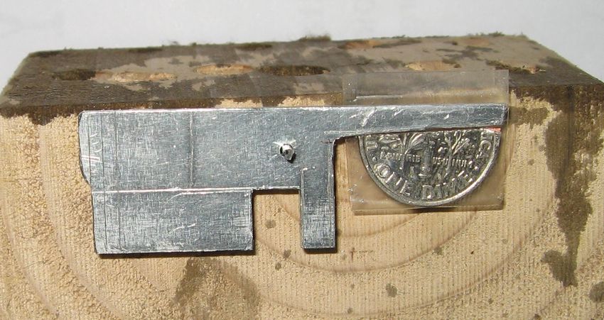
The opto coin switch is made from a OPB802 opto diode-transistor interruption detector that is switched by a tab on a metal balance beam.
Do not operate the opto-coupler without the 2SC2909 in place as its base-to emmitter diode protects the low Vceo phototransistor from destruction. My prototype switch is shown in the following photogragh, but the following drawing shows a slightly different layout that I feel would be simpler to assemble and align. Balancing the beam was done with half of a dime taped to the beam. The beam is suspended on a brad nail driven into a block of wood. By filing the counterweight end of the beam until blance is reached, triggering with a whole dime is assured, and return of the beam to the at-rest position is also assured.
Opto balance-beam switch original version
|
Opto balance-beam adjustment
|
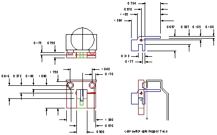
Opto balance-beam switch dimensions
Improved version
|
First magnetic switch
This coin switch was made from a normally open reed switch. It eliminated the transistor and resistor of the opto circuit and was much simpler than the opto circuit.
A simple balance beam was moved by the dropping coin and a magnet on the balalance beam tripped the reed switch.
The problem was the magnet was heavy, even though it seemed a small powerful one. To get a dime to move the balance beam, the magnet had to be very close to the balance beam shaft. The reed switch position adjustment to get a reliable off-on transition was very difficult. The difference in angle between on and off seemed large enough that a dime might slip though the hopper without triggering the coin detector.
I laid out a new circuit board for the magnetic switch, but never built it until I made mag-switch version two. Although this switch was a failure, It gave me a starting point and an experimental test bed for making the current magnetic-reed switch.
Magnetic coin switch
|
Copyright Dale Thompson,
September 21, 2014 through
last revision on October 21, 2014