My mustang spent the winter in the garage, and ended up with a un-chargeable battery this spring. Now, the battery was only about 6-months old, so I began research how batteries die and what to do about it. This project came out of that research.
It seems I did everything wrong. I let the battery go completely dead, no float charging. I started the car a few times during the winter, but never allowed the battery to get fully recharged. I charged the battery incorrectly with a bench power supply. The result is a battery with sulphonication.
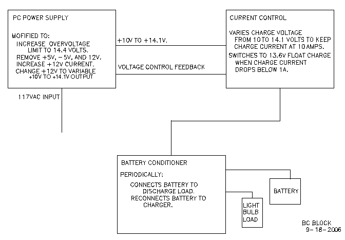
So, what I wanted to build was a battery charger that would charge a battery at about 10 amps if it was very discharged, and then switch to a float charge of about 100 ma when the battery was nearly charged. I wanted to use one of the old PC power supplies that I have lying around as the power source for the charger. In addition to the charging and float maintenance, I wanted to periodically apply a load to discharge the battery slightly and follow the discharge with a re-charge.
In the middle of this project I found information on desulfators and began exploring using a desulfonator instead of the pc power supply charger. After building this charger I started building a combination desulfator-charger.
Click here to go to a new page for the desulfator.
A PC power supply was modified to supply between 10 and 14.1 volts.
The +5v inverter transformer windings and filter elements were disconnected, as was the +12-volt rectifier and all the -12 volt and -5 volt circuitry. The 12-volt inverter winding was then connected to what had been the +5-volt high-current rectifier. With this arrangement the inverter should be able to produce 10 amps at +14.1 volts with 200 watts input. The 12-volt inverter winding, however, may not be sized to deliver that much current continuously.
The over-voltage circuit was modified to shut down the inverter at >15 volts. The over-current circuit was left alone. Voltage control is a voltage divider connected to the supply output, and was modified with three switch points : 10 volts, 13.6 volts, and 14.1 volts.
A charging-current control circuit was built to set the power supply voltage to correctly charge a battery.
Current to the battery is monitored by passing through a .1-ohm resistor. Opamps compare the resulting voltage to references and feed back to the power supply. When the battery is very discharged the power supply voltage is dropped to as low as +10 volts to limit the charging current to 10 amps and keep from tripping the power supply over-current circuit. As the battery accepts some charge, the supply voltage increases and current is held at 10 amps. When the supply voltage gets to 14.1 volts the voltage stops rising and the charging current starts to decrease. At a charging current of 1-ampere the battery is essentially charged and the power supply voltage is reduced to 13.6 volts to maintain a float charge current of about 100 ma.
When a battery is left unused for a long time, even with a float charge, it degrades due to the electrolyte stratification. To prevent this degradation, a circuit was built to periodically discharge the battery a little and then re-charge it. The bubbles and heat produced during the re-charge stir up the electrolyte.
Most PC power supplies have very similar circuits. In the References section below there are a number of links to sites that describe modifying the computer supplies for powering 13.8 volt equipment. I only traced the circuit of the particular power supply I used enough to be able to modify it to put out 14.1 volts.
After removing the -5 and -12 volt components, I disconnected the +5 volt transformer winding and jumpered the circuit board to connect the 12 volt winding to the high current rectifier. Next I modified the over-voltage circuit.
|
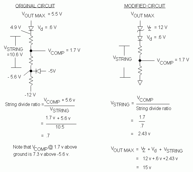
The over-voltage circuit compares a reference voltage of 1.7 volts to a voltage tap on a resistor string. The bottom of the string had a diode to -5 volts and a resistor to -12 volts. This placed the junction of these two components at -5.6 volts when power supply voltages were normal. The top of the string was connected through a diode to +5 volts. The total voltage across the string was [5.5v - .6v diode drop + 5.6v] = 10.5 volts The string was tapped to produce .73 times the input. So (.73 x 10.5 v) -5.6 = 1.7 volts. I connected the junction of the two negative voltage components to ground, which in effect raised the bottom end of the voltage divider string by 5.6 volts. Since the top end of the string originally went to the +5 volt line, but now goes to the +14.1 volt line, I put a 12 volt zener in series with the 5 volt input. So the voltage output from the string becomes .73 x (14.1v - 12v - .6vdiode drop) = 1.1 volts. Over-voltage turns the supply off at 14.9 volts [ .73 x (14.9v - 12v - .6v diode drop) =1.75 volts.
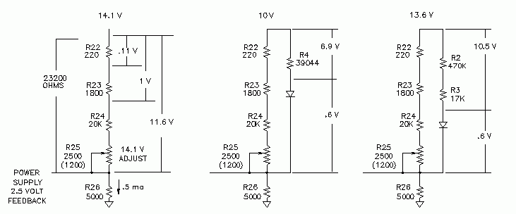
The PWM controller chip (TL494) controls the inverter pulse width to keep the feedback voltage at 2.5 volts. For the power supply I modified, there was a resistor string connecting to +5 volts, +12 volts, and ground. Removing the +5 volt resistor and recalculating the +12 volt for a +14.1 volt connection was pretty simple. This resistor string was further divided to provide the range switching for the current controlling portion of the battery charger.
When I started this project, I searched the internet for a battery charger design to construct. I selected
a battery charger at Anthony van Roon's site by Jan Hamer, but then started to think about possible changes. I didn't have the voltage regulator or the high-current transformer on hand, so I would have had to design around the regulator and buy or rewind a transformer. I am a miser; ask my wife. I did have a number of old PC power supplies, so I decided to modify the circuit to control the power supply instead of the series voltage regulator chip.
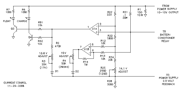
Opamp U1B keeps the charging current at 10 amps until the battery voltage reaches 14.1volts. Opamp U1A sets the charger output voltage to 13.6 volts after the charging current drops to 1.1 amps with a 14.1 volt charge voltage.
U1A-OUT is low until the current through R21 is less than 1.1 A. D1 is back-biased .
U1B-OUT is high for a discharged battery. Resistor R4 through D2 is put in parallel with the R22/R23/R24/R25 resistor string, which with R26 determines the power supply feedback voltage. U1B-OUT turns on enough to reduce current flow to the divider string and vary the feedback voltage. The output voltage of the power supply varies between 10 and 14.1 volts until the current through R21 produces 1 volt. This is 10 amps of charging current. The current is held at 10 amps as the battery charges by U1B-OUT turning on and reducing more of the current going to the divider string. The power supply output voltage thus increases to keep the power supply feedback voltage at 2.5 volts.
U1B runs out of control range when the power supply reaches 14.1 volts. The power supply feedback is set by R25 in the R22/R23/R24/R25/R26 resistor string.
As the battery continues to charge, with the voltage fixed at 14.1 volts, the current through R21, and the voltage across it, decreases. When the voltage across R21 drops below 110 mv, which is 1.1 amps charge rate, U1A-OUT goes high. This allows R2 and R3 to be put in parallel, through forward-biased D1 with the R22/R23/R24/R25 resistor string, and sets the charging voltage to 13.6 volts for "float" charging.
My apologies for the confusing description of the counter string that follows. In order to optimize board space, I had to bounce the ripple count from U2A, to U3A, to U2B, to U3B.
From the current-control circuit, the charging current passes through a relay in the battery conditioner to the battery. The relay switches between applying the charging current and discharging the battery through a loading light bulb.
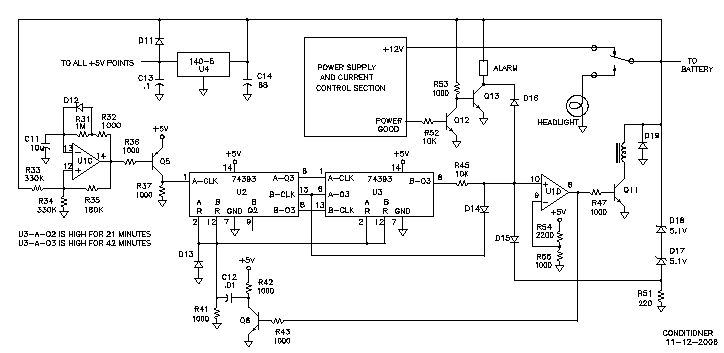
U1C is a 0.1-hz relaxation oscillator, slightly non-symmetrical due to D12, which is there to make the falling edge of the clock pulse to the 74393 counter faster. Seven and one-half days later, the Q3 output of the fourth counter (second counter in the 74393 dual counter,U3) goes high and applies +2.4V to R45. The other end of R45 is clamped at 0.8 V by the low output of the second counter (Q3 output of the first counter in U3). Twenty-one minutes later, the output of the second counter goes high for 42 minutes and unclamps R45, and +2.4V is applied to U1D. The output of U1D swings high, turning on Q11 and the relay. The battery discharges through a car headlight high-beam bulb for 42 minutes, or until the battery voltage drops below 11.6 volts. When the voltage across R51 drops below 11.6 volts, D15 pulls the voltage applied to U1D below the +1.6V reference at the junction of R54 and R55.
Q6 was turned on when U1D turned on the relay. This discharged C12. Now, when U1D output drops low, Q6 turns off and the capacitor applies a positive reset pulse to the counters. The conditioning cycle begins again as the relay connects the battery to the charging current.
If the power supply circuit fails, the battery could be connected to the headlight bulb and discharge when there will not be a source to re-charge the battery after a discharge. Additionally, the battery, would continue discharging un-noticed through the battery-charger electronics if the power supply really does go south. A low-current-draw alarm is in place to alert me if this situation occurs and disconnect the discharge load. Transistor Q12 is turned on by the power-good signal from the power supply and keeps Q13 and the alarm off. If the power supply fails, the loss of the power-good signal turns on the alarm, which derives its power from the battery, and pulls the input of U1D low to release the discharge relay. The counter count state is preserved by the +5V being taken from the battery. So, if the power supply failure was just a momentary power glitch, the count will continue as soon as the power supply restarts.
After the +5V, -5V, and -12V components were removed from the pc power supply, there was room to add a small circuit board for the added circuitry. The headlight bulb was mounted in a small box on the front of the PC power supply case. It was constructed of perforated metal and gets cooled by the air coming out of the pc power supply. The added box also contains the current-sense resistor, R21, and the charge-discharge relay.
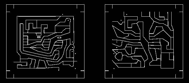
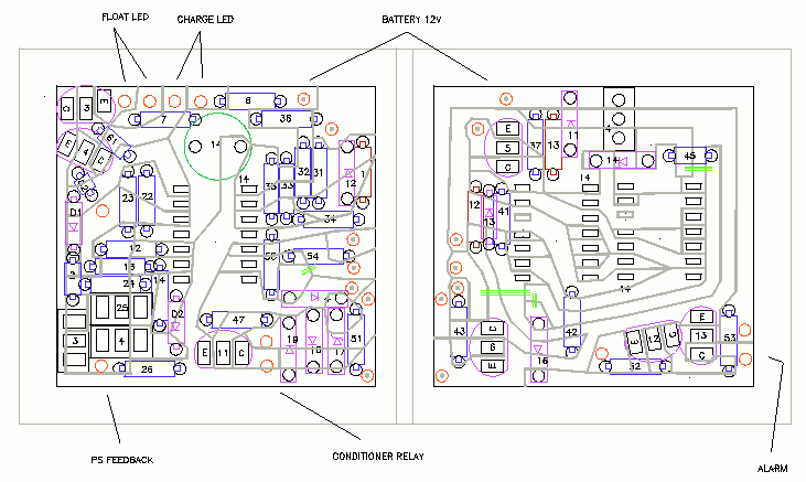
A small printed circuit board holds most of the components added to the pc power supply. The board was etched using the photo paper technique referenced on my website main page. I have been looking at using a PC board schematic-capture, drawing, and autorouting software, but the learning curve for these specialized packages is high for someone who just does maybe two small boards a year. Currently, I use a manual method that involves three software programs. However, I use these three programs in other areas so I am already able to manipulate the programs.
|
I draw the layout using DesignCAD, then split off the layer that has the board cuts needed and mirror the image. Next, I print the cut-layer to a virtual printer. The virtual printer uses a postscript printer driver and the program Ghostscript. The virtual printer generates a PNG file that I open with Irfan View. Using Irfan View, I change the the image to a negative image and print it on inkjet photopaper with a laser printer. Finally, I iron on the image and etch the board. You can get all the details by going to the
Random Links That Don't Fit Any Place section of my main page.
I made a 0.1 ohm resistor for R21 out of nichrome wire from an old dryer heating element. Nichrome wire of .052-inch diameter is .2595 ohms per foot, so 4 turns of it on a 3/8-inch diameter form gives 0.1 ohms.
To make sure the sense voltage was not affected by the solder joint resistance, I used Kelvin contacts. Four wires were soldered to the nichrome wire, two for voltage sensing and two for passing current from the power supply to the battery. One of the Kelvin-contact wires also is the power source for the circuitry on the added pc board, so the voltage sensing wires are not purely Kelvin contacts.
I soldered wires to the nichrome wire by sanding the wire and using a zinc chloride containing plumbers flux. This acid flux requires a thourough post soldering clean using a solvent to get rid of the wax in the flux, and a long soak in a solution of sodium bicarbonate, detergent, and warm water to neutralize the acid.
