As before, the board was made by scoring two parallel lines on the the copper with an Xacto knife for each needed separation, then peeling the copper between the lines off of the circuit board. After the separations were made, the board was sanded, and then, tinned using a water-soluable solder paste. All components were surface mounted. The screw terminals shown in the layout were not needed for this phone so wires were just soldered directly to the track.
Click on the photos below for construction details and photos.
 Antisidetone Circuit |
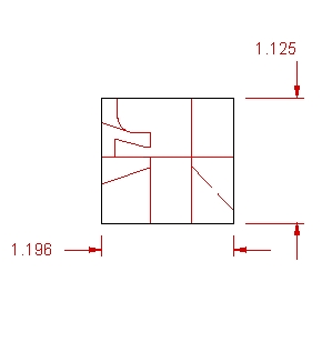 Board Artwork |
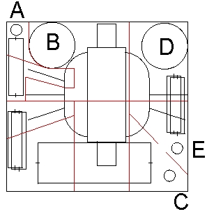 Component Placement |